-
Notifications
You must be signed in to change notification settings - Fork 6
UserInformation
When SEE is started, a dialog appears in which the network configuration can be selected.
SEE can be started in two modes:
- Host: Starts a server and a local client. The server manages synchronizes the different clients so that all clients have always a consistent world.
- Client: Starts a local client connecting to a remote server.
If one of those two options is selected, the scene is loaded and the game begins.
There must always be one server. There may be multiple clients connecting to this server. If you want to run SEE for a single user only, you still need to start a server and local client by selecting Host.
If clients connect via the Internet, make sure that your server is visible and the ports are available for remote access. The server and all clients must agree on the server address and ports.
The IPv4 address and the ports of the server can be configured under Settings.
-
Server IPv4 Address: The IPv4 address of the server in the numeric format
<number>.<number>.<number>.<number>where is any number between 0 and 255. SEE currently does not support names for addresses. For a local host, you can use127.0.0.1. - Server TCP Port: The TCP port number where the server listens to incoming requests of its clients. The port must be available and open. A port number must be in the range 0..65535, although some port numbers are reserved. For more information on TCP ports, see here, for instance.
- Server Action TCP Port: The TCP port number where the server listens to incoming action requests of its clients. It must be different from the Server TCP Port. This additional port is needed for technical reasons at presence. In the future, SEE may require only one port.
-
Voice Chat: SEE allows players to communicate via voice chats. There are currently three options:
- None means no voice chat system. Players cannot communicate via voice chat.
- Dissonance is a peer-to-peer voice chat system that routes the voice signal only between this server and its clients. It our recommended choice if a voice chat should be available.
- Vivox is a voice chat system provided by Unity. The voice signal will be routed through a Unity server. To learn more about Vivox, see here.
If you execute SEE on different machines that are connected via Internet, you might need to configure your firewall.
Always make sure, that the firewall of Windows allows the Unity Editor to start the server as follows:
- Open
Windows Defender Firewall with Advanced Security(German:Windows Defender Firewall mit erweiterter Sicherheit). - Select
Inbound Rules(German:Eingehende Regeln). - Find the Unity Editor (e.g. Unity 2022.3.18f1 Editor) entries (there should be two).
- Delete the entry with the red blocking symbol.
- Double-click the entry with with green tick symbol.
- Select
Advanced(German:Erweitert) and enableDomain,PrivateandPublic(German:Domäne,PrivatandÖffentlich). - Apply your settings.
If you start SEE from the Unity Editor, you might also need to set the toggle Allow Remote Connections in the component Unity Transport of the NetworkManager game object in the SEEStart scene and enter the server IP in the field Override Bind IP (optional) below with the same server IP you provide in the Address field.
A graph must have been loaded. Then list the available metrics in the loaded graph by pushing button List Node Metrics in the Inspector when selecting a game object with a code city component attached to it. The node metrics will be listed in the console of the Unity editor.
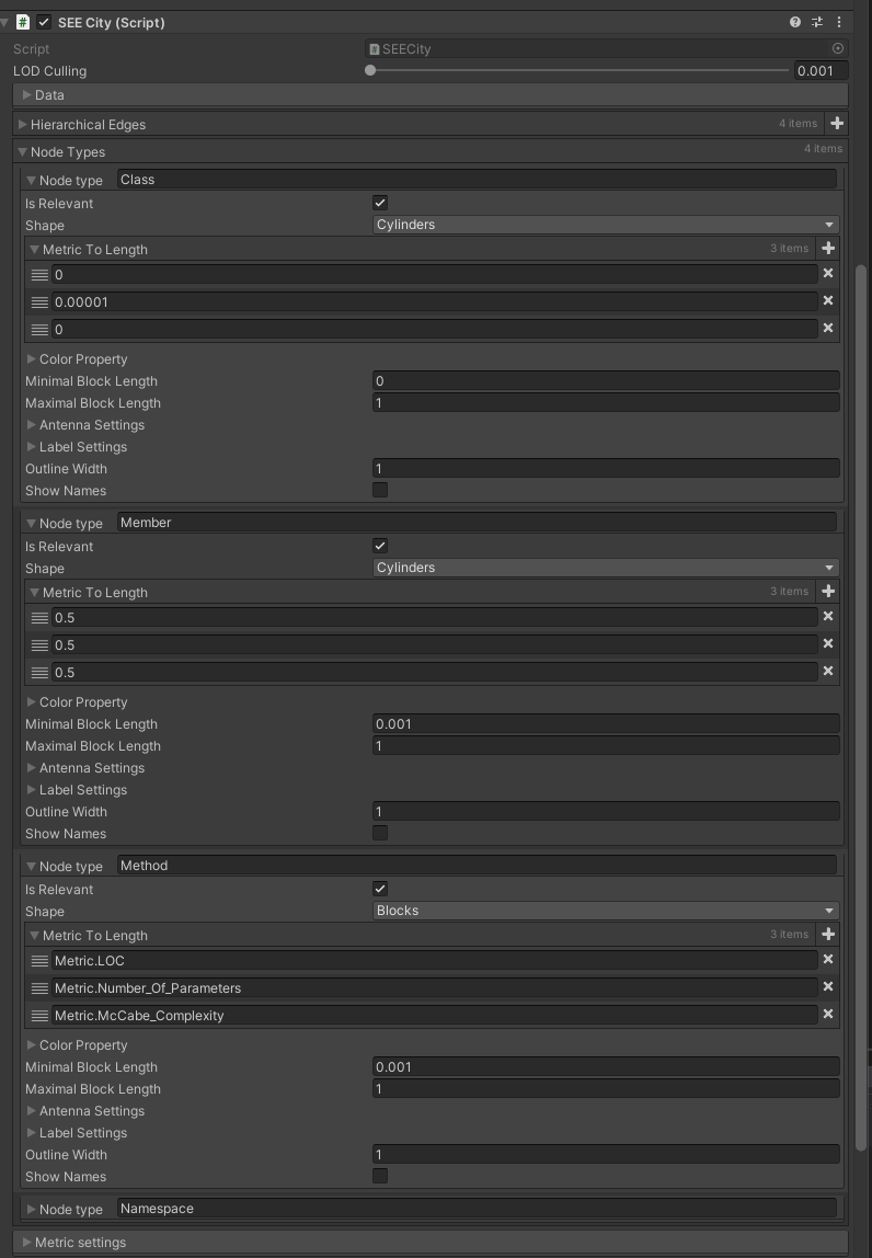
To specify which metric determines a particular length of a shape drawn for a node, go to section Node Types/Node Type for the respective node type and add the metric name to Metric To Length list. Uniformly to Unity's co-ordinate system, the first entry specifies the x axis (width), the second entry the y axis (height), and the third entry the z axis (depth).
Alternative to a metric name, you can enter a constant float number, in which case that value will be used as a fixed length.
Note: a metric value as well as a constant float will be clamped into the value range defined by Minimal Block Length and Maximal Block Length.
You need to specify at least three metrics for each node type. Some kinds of shapes (e.g., polygons and spiders) accept more metrics. If a node leverages fewer metrics than specified, the surplus metrics will be ignored.

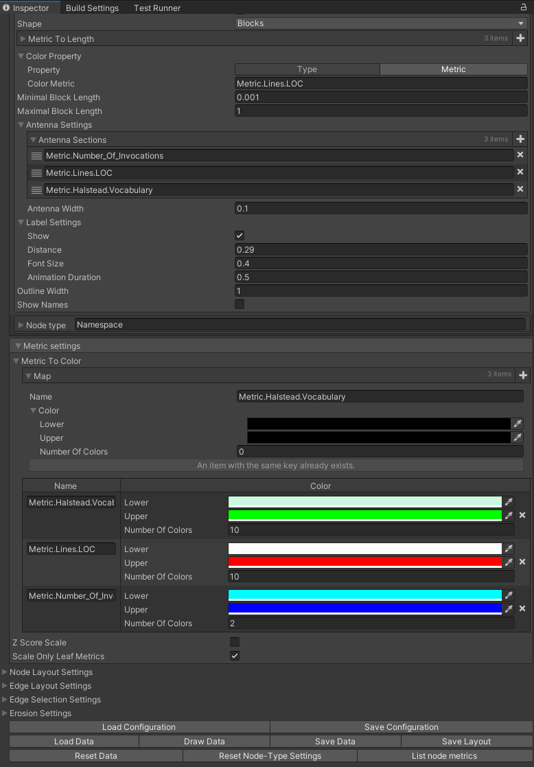
- Define the name of a node metric and its color range (lower, upper color and number of colors in the color range) in the Metric To Color section.
- Add the metric name to where you want to use it:
- To use the metric to determine the color of a node type: Go to section Node Types/Node Type for the respective node type and select the property toggle Metric and add the metric name to Color Metric in the subsection Color Property.
- To use the metric to determine an antenna segment of a node type: Go to section Node Types/Node Type for the respective node type and add the metric name to Antenna Sections in the subsection Antenna Settings.

- Go to section Node Types/Node Type for the respective node type and select the property toggle Type in the subsection Color Property.
- Pick the Type Color for the node type.
- Toggle on/off By Level. If By Level is set, the Type Color will be varied by the level of the node in the node hierarchy of the underlying graph. This way, two nested nodes of the same node type can be distinguished visually. The color range for this variation starts at a lightened variant of Type Color and ends at Type Color. That is, the node with the lowest level has Type Color as its color. If By Level is not set, all nodes of the same type have the same Type Color.
