Printed Circuit Board
The prototype board is a 4-channel acquisition circuit which chains analog signal processing elements to test them. This board was not intended to make the signal adequate for digitization and so some elements described bellow are not integrated on it yet but have been tested with simulations. The intended production board’s signal processing chain is shown on figure 2 and the prototype board’s signal chain is shown on figure 1. The input for both boards is five electrodes connected to the patient’s head. Four of those electrodes are connected to the channel inputs and the fifth one acts as a reference against which the signal of the channel electrodes is measured.
The electrode voltages have amplitudes in the µV range from single digits to triple digits. This means that with an analog pipeline of gain 1000, the signal should not exceed a 1V amplitude. This is good for digitalization because it means that the signal fits into the 0 – 3.3V range of microcontroller ADCs and that it won’t saturate the signal chain’s op amps, which are powered with ±5V for the prototype board and which will be powered with ±3.3V for the production board.
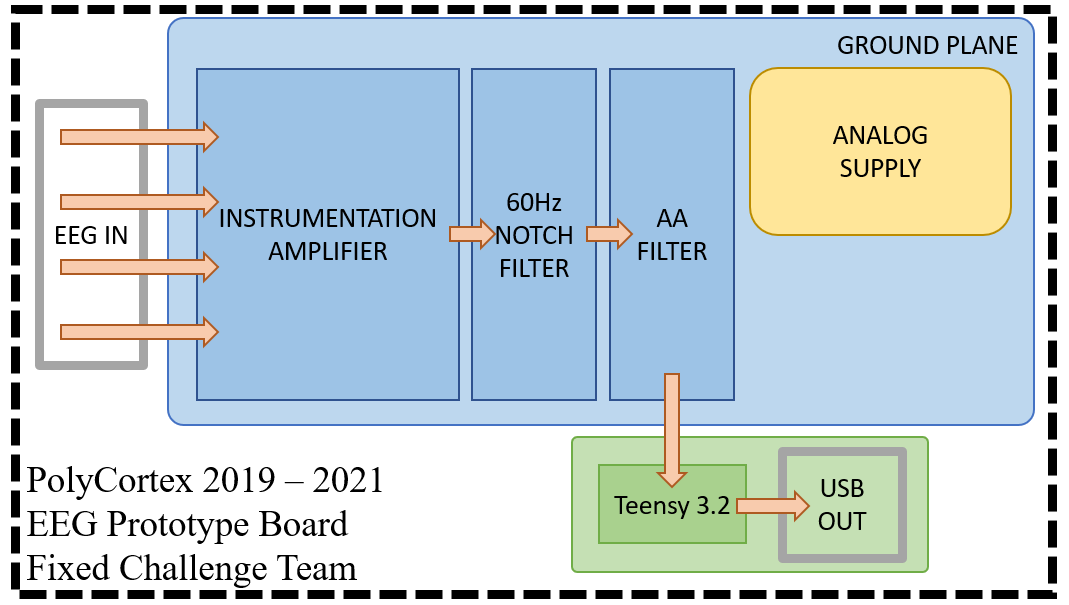 Figure 1: Circuit for the Prototype Board
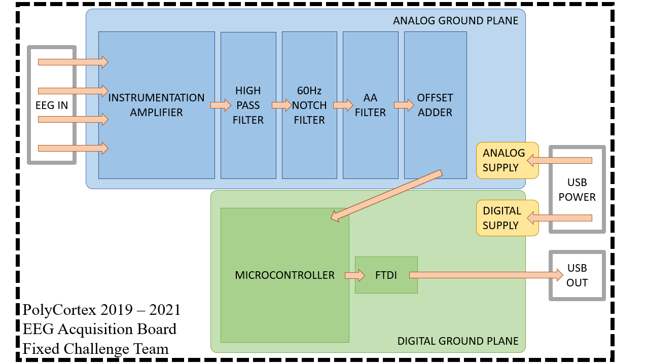 Figure 2: Planned Circuit for the Production Board