-
Notifications
You must be signed in to change notification settings - Fork 637
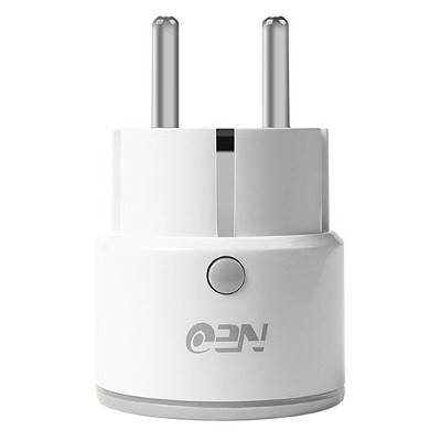
Hardware NEO COOLCAM NAS WR01W

| Property | Value |
|---|---|
| Manufacturer | Coolcam |
| Product page | AliExpress Link |
| Wiki page | |
| Build flag | NEO_COOLCAM_NAS_WR01W |
- Rated voltage: AC 110-230V
- Rated current: 10A (2300W)
- Product size: 65x43x43mm
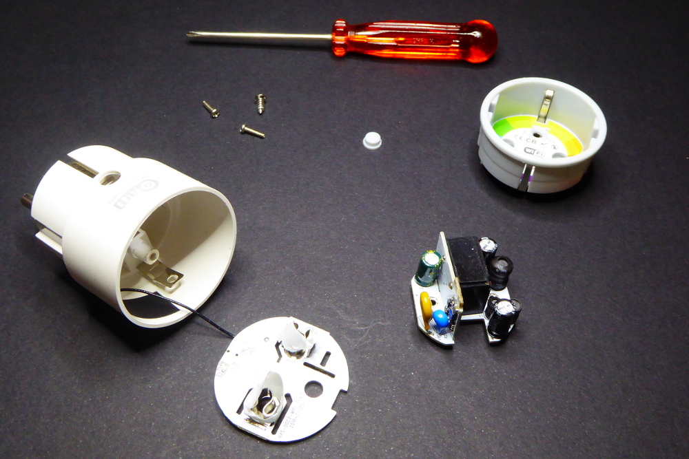
Flashing the Neo Coolcam NAS WR01W can be done Over-The-Air (OTA) using Tuya Convert. Download the espurna image file for the Neo Coolcam WiFi WR01W and replace 'thirdparty.bin' with the downloaded version. You can also flash the firmware through the available serial port, you will have to disassemble the unit.

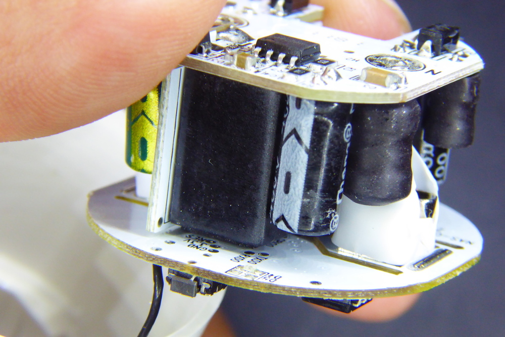
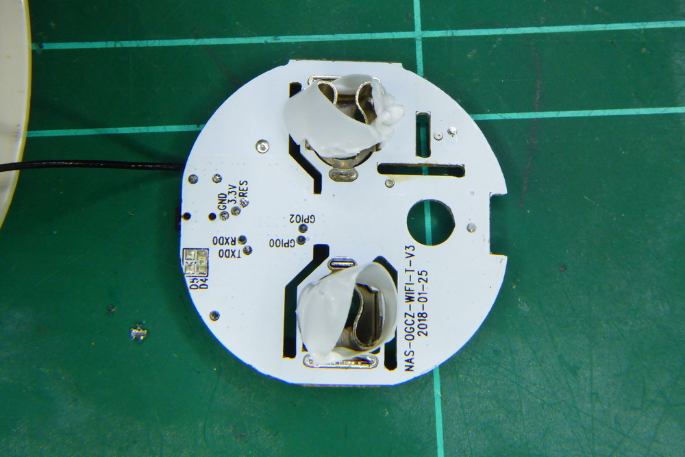
The electronics are split into 3 different PCB for mains connection, power supply and logic. To be able to flash the ESP8266 chip you have to solder 5 small pads in the back of the top layer (the logic one), but those pads are hard to reach because the relay top (soldered to the bottom layer) is very close to them.

So the best option you have is to remove the top layer by desolder the 6 pads that connect it to the middle PCB. Once removed the procedure is the same as with other devices: tin the pads a bit, solder some small cables to it and flash it. The pads are appropiately labelled as GND, 3.3V, TXD0, RXD0 and GPIO0.

Thanks to @ilker-aktuna for suggesting a video walkthrough of the process:
https://www.youtube.com/watch?v=CV8Y61gEQpQ (#2450)
Use an UART board for serial connection and flashing. Connect wires as follows:
- Board - UART
- GND - GND
- 3.3V - 3.3V
- RXD0 - TX (note crossing rx to tx)
- TXD0 - RX (note crossing tx to rx)
- GPIO0 - GND (Disconnect after flashing)
Note from other users:
- Connection GPIO0 to GND did not help - flashing did not work. I had also to connect RST pad to 3.3V. After that - flashing worked perfectly even without RST connected to 3.3 V (from second flash)
in Platformio for tasmota flag change from 1MB to 8MB is needed, otherwise flash fails. build_flags = ${esp82xx_defaults.build_flags} -Wl,-Teagle.flash.8m.ld
in Arduino IDE, board selected - "Node MCU 1.0", standard
- LED = GPIO4 (D2 NodeMCU)
- RELAIS = GPIO12 (D6 ModeMCU)
- BUTTON = GPIO13 (D7 NodeMCU)
Those are the defaults in prebuild binaries.
- LED = GPIO13
- RELAIS = GPIO14
- BUTTON = GPIO0
This needs to be configured for example in code/espurna/config/custom.h:
    #define LED1_PIN            13
    #define RELAY1_PIN          14
    #define BUTTON1_PIN         0
And then binary must be build manually.
If you're looking for support:
- Issues: this is the most dynamic channel at the moment, you might find an answer to your question by searching open or closed issues.
- Wiki pages: might not be as up-to-date as we all would like (hey, you can also contribute in the documentation!).
- Gitter channel: you have better chances to get fast answers from project contributors or other ESPurna users. (also available with any Matrix client!)
- Issue a question: as a last resort, you can open new question issue on GitHub. Just remember: the more info you provide the more chances you'll have to get an accurate answer.
- Backup the stock firmware
- Flash a pre-built binary image
- Flash a virgin Itead Sonoff device without opening
- Flash TUYA-based device without opening
- Flash Shelly device without opening
- Using PlatformIO
- from Visual Studio Code
- Using Arduino IDE
- Build the Web Interface
- Over-the-air updates
- Two-step updates
- ESPurna OTA Manager
- NoFUSS
- Troubleshooting
- MQTT
- REST API
- Domoticz
- Home Assistant
- InfluxDB
- Prometheus metrics
- Thingspeak
- Alexa
- Google Home
- Architecture
- 3rd Party Plugins
- Coding style
- Pull Requests