Home
Welcome to the robotic_vision_final_project wiki!
The goal of this project was to build a simple robot that could balance a ball on a platform while simultaneously controlling the ball's position, using a raspberry pi, an Arduino Pro Mini, and two servo motors. The RPi 3 is used to run the computer vision and control algorithms, while the RPi camera would be used for position feedback for the controller. The Arduino is only used to generate PWM for the servo motors. The RPi computes position using the camera feedback, runs the feedback through a PID or LQR controller, and sends out servo commands to the Arduino Pro Mini which controls the servo positions.

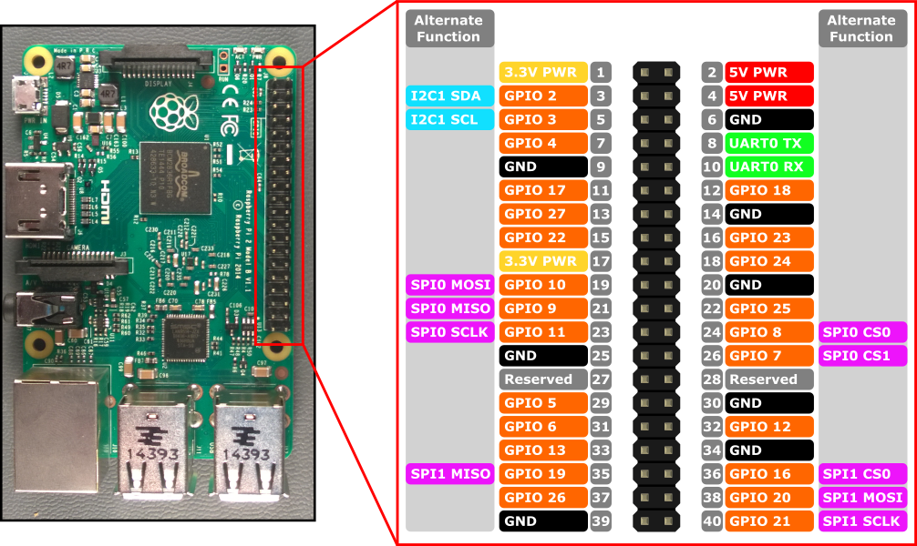
- Raspberry Pi 3
- 2 X Servo Motors
- Raspberry Pi Camera
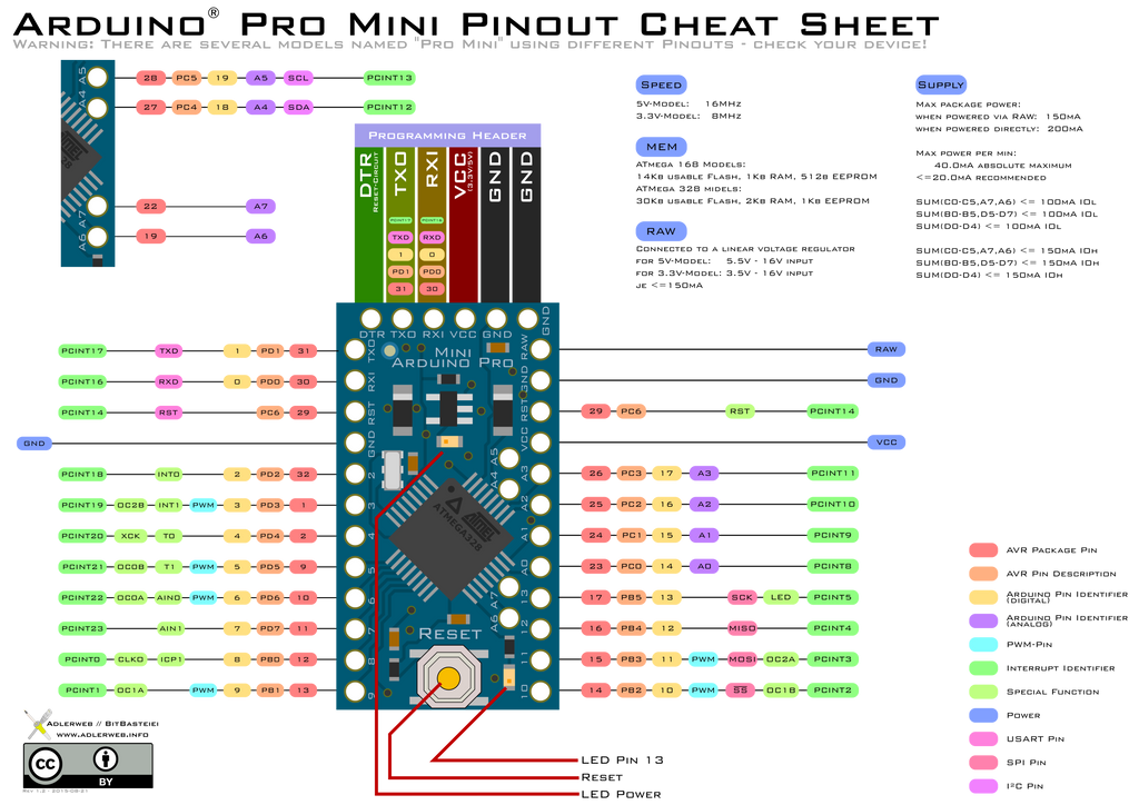
- Arduino Pro Mini
- DXF for Platform Build
- Universal Joint (table top pivot)
- Miscellaneous Electronics Stuff
- jumper wires
- breadboard
- capacitors
- LEDs
A note before I discuss the dynamics of the system. The only reason to develop dynamic equations is to come up with a model that can be used for model based control or simulation. Simulating the robot was out of the scope of this project, so I ignore that, but I was interested in using LQR for the controller. Since LQR is model based control I needed the dynamics of the system which were relatively straight forward.
I first split up the dynamics into two equations: 1) the XZ plane and 2) the YZ plane.The image below shows a free body diagram of the two side views.

This of course is a very broad simplification of the actual dynamics. When the full equations of motion are linearized they simplify quite nicely, and the separate 2-D views are an appropriate approximation. and
are defined as positive rotations about the x and y axes respectively. Thus the forces acting on the ball in the x and y directions are:
and
Using these two equations the state space representation is shown below as:
Using OpenCV on the RPi was not as straight forward as it usually is in Linux. The first obstacle is downloading it on the RPi, but there are some good helps online if you google 'how to install OpenCV on Raspberry Pi 3'. The second obstacle was figuring out how to access and get information from the RPi camera. The link that helped me the most in overcoming this obstacle is below:
https://www.pyimagesearch.com/2015/03/30/accessing-the-raspberry-pi-camera-with-opencv-and-python/
I had to modify the image size in order to get the frame rate I wanted. I wanted more than 30 frames per second, but when I first turned on the camera and ran my code, I was getting frames at about 5hz. I needed more so I had to shrink my image size down quite a bit. The lowest resolution I used was 160x128. This still gave me a good enough resolution for positioning. A length of 128 pixels was equivalent to about 6 inches, which meant that my position resolution was about 0.047 inches. This was most likely another cause for noisy position estimates which ultimately affected the noise in the servo motors.
Once I had camera data, I was able to do use the CamShift algorithm to track the position of the ball. The only thing that CamShift needs to create a bounding box is a mask, or a binary image. I found it difficult to get a good mask using HSV images. I found the most effective method for creating a mask was to place a white piece of paper on the platform and use a black ball to obtain a high contrast between the platform and the ball. I then thresholded the image so that only black colors would be seen in the binary image. There was still some noise due to shadows from the camera support frame, so I had to use OpenCV's erode and dilate functions to get rid of noise. This cleared up the image enough to allow for good position estimation.

A link to the vision code for the project is listed below:
https://github.com/natd89/robotic_vision_final_project/blob/master/video_cam_shift.py
We can now use the equations of motion to form an LQR controller. In order to do this I had to install the python control systems library found at http://python-control.readthedocs.io/en/latest/intro.html. The function to use is the K = control.lqr(A,B,Q,R). The Q matrix is a waiting matrix on the states and is the same size as A. R is an input waiting matrix that is a square matrix with dimensions matching the total number of inputs u. The input u is calculated as follows, u=K*x, where x equals your state vector. The following link shows the code for my LQR controller.
https://github.com/natd89/robotic_vision_final_project/blob/master/lqr_control.py
Here's a video of the LQR controller in action (I didn't spend a lot of time on tuning it):
LQR wasn't working as well as I had hoped, and I'm pretty sure its due to errors from manufacturing (this was handmade, so errors can be expected). Because of errors introduced by manufacturing the ball just couldn't get to the 0 position without trying to really fidget with tuning parameters and servo motor offsets, etc. I decided to move to a PID controller since it wouldn't send specific servo positions but would just tell the servos if they needed to change by a certain amount. The code for the PID controller can be found below:
https://github.com/natd89/robotic_vision_final_project/blob/master/pid_control.py
Here's a video to show that the PID controller does perform better...probably because it was much easier for me to tune than the LQR controller.
Most of the performance improvement was due to the integrator getting rid of most of the steady state error. The servos jitter more than I would like them to, but this doesn't seem to be an issue with the PWM signal. Because the position feedback is noisy (even though I low-pass filtered it), the servo commands are noisy. The servos were doing what they were told to do. I initially had the PWM generated by the RPi, but the PWM generated by the RPi is software PWM and not hardware PWM. The difference is that hardware PWM has consistent timing, but software PWM can be interrupted if running multiple programs at a time on the RPi. I overcame this by outsourcing the PWM generation with an Arduino Pro Mini. I would send servo commands to the Arduino via I2C (pins 3 and 5 on the Raspberry Pi, and pins A4 and A5 on the Arduino), where an interrupt would detect the commands and generate hardware PWM signals. This dramatically improved the servo control.
Here's the servo command code used on the Arduino:
https://github.com/natd89/robotic_vision_final_project/blob/master/arduiono_i2c.ino