- Project details
- Compatibility
- Operation manual
- Frequently asked questions
- Building
- Creating a .ioc file from scratch
- Additional Documentation
- Pending or non working features
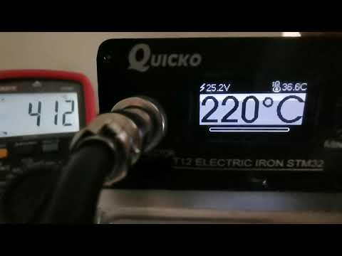
Video of operation here: (Project in active development, the features will change continuously)
- This project started by forking PTDreamer's firmware. Since then it became a separate project.
- Developed on STM32Cube IDE. Basic configuration is easily done in CubeMx (Included in STM32Cube IDE).
- Unified codebase, different hardware support based on profiles, very few files need to be changed.
- Supports all display modes: I2C, SPI, software and hardware+DMA (When connected to hardware pins).
- Uses u8g2 graphics library.
- Dynamic screen loading to save RAM resources.
- Extremely customizable, lots of options available.
- Code highly optimized to avoid wasting cpu power, slow devices still run great.
The actual requirements are 10KB RAM and 64KB flash. Don't even try if your MCU has less than that.
The BOARDS folder has the board code profile, schematics and/or board pictures for quickly identify your hardware.
Current working controller:
- Quicko T12 [STABLE]: Profiles for STM32F072 and STM32F103.
- JCD T12 [STABLE]: Different board layout, but it's 100% the same as the KSGER v2. Use that firmware.
- KSGER v1.5 [STABLE]: Profile for STM32F103 (There are no other known CPUs used in this board).
- KSGER v2.x [STABLE]: Profile compatible with all STM32F101/2/3xx. Use 101C8 profile.
- KSGER v3.x [STABLE]: Profile compatible with all STM32F101/2/3xx. Use 101C8 profile.
Keep in mind that you can't trust the version shown in the original firmware to identify your board.
Go to BOARDS/... schematics folder and compare the pictures.
There are several compatible/cloned boards in the market that will work fine with Ksger profiles.
First, make sure to read the Operations guide!
Be warned, usually the MCU will be read-protected, so you won't be able to read its contents, only erase it.
For KSGER boards, some can be found over internet.
The simplest way to not loose the original FW is actually to buy a new MCU, replace it, and store the original MCU in a safe place.
Any difference in the pinout will require firmware tuning, although one of the main proposits of this firmware is easing that.
There are some hacks / vulnerabilities that can be used to backup protected firmware, more details here:
STM32 power glitching timing attack
Download the binary STM32SolderingStation.bin already compiled from the /BOARDS folder and flash it using stlink.
There's no support for custom bootloaders, and there won't be, as flash is almost full in 64KB devices.
Use one of these ST-LINK clones ($3 or less), refer to the schematics for the SWD pinout.
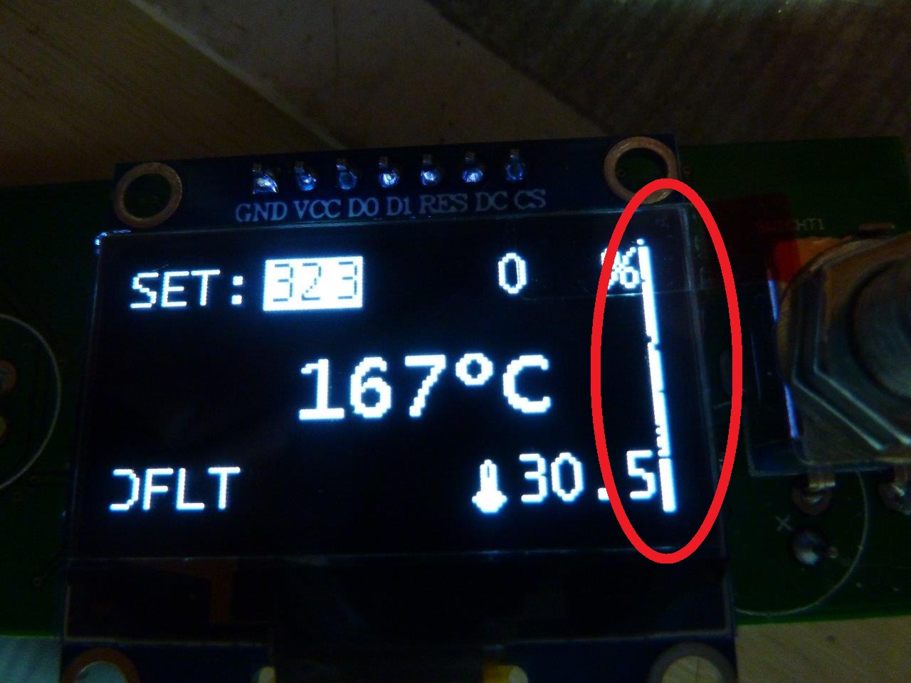
If the display has right/left line like this picture: Go to System menu / Offset and adjust the value until it's centered.
By default, never modify any PWM / Delay settings in the Iron menu. Doing so may cause such issues.
Also, new tips are often unstable, leading to temperature jumps.
Don't try to calibrate the tip in this state, neither set a high temperature, because it could go under control.
They usually settle after some burning time. It's recommended to set a medium temperature (250-300ºC) and leave like that for 15-20 minutes until it stabilizes.
If the temps are still unstable, try increasing the Iron/Delay option, allowing more time for the temp signal to settle.
A damaged, loose or defective connection in the handle will also cause this issues. Ensure the contacts are clean.
There have been problems with some board/stations like:
- Noisy power supply
- Broken / badly soldered capacitors
- Bad Op-Amp
- Bad 3v3 Regulator
Buying a cheap high temperature meter is highly recommended!
These boards can have pretty different readings and tolerances. Even between T12 tips.
So the factory calibration is intentionally set lower than real, to avoid possible overheating problems.
Once you set the firmware, go to calibration and set there the real temperature measured with the external probe.
Ensure to read Calibration menu first!.
To calibrate, go into Calibration / Start.
Attach the temperature probe before proceeding!
If the difference between measured and real is higher than 50ºC, the calibration will be aborted, telling you to go into Calibration / Settings and manually adjust the values.
The calibration settings menu has 3 calibration steps: 250, 350 and 450ºC.
When you edit the value, the it will be applied in real time, so be careful!
The iron will be turned off if no setting is being edited.
Adjust each value until is close to the target temperature.Repeat for each step and save.
This values are only used by the calibration process, to prevent burning the tip if your board reads too low.
After adjusting, repeat calibration, this time it should work correctly.
The calibration results for the current tip can be seen in the tip settings menu.
In the case you lose, wipe or reset the data, you can go back into that menu and adjust the values based on previous calibration results.
Otherwise, they aren't meant to be another calibration menu! Only for viewing (Ex. reporting calibration results) and making backup/restore of the values.
After fully reading the documentaion, if you still have problems or doubts, please ask in the EEVblog thread:
https://www.eevblog.com/forum/reviews/stm32-oled-digital-soldering-station-for-t12-handle
Video of building steps:

If you use an existing project template and modify it, the changes must be reflected in /Core/Inc/board.h.
All the project code takes the data from there. The file it's pretty much self-explaining.
So, any changes you make in CubeMX, ex. use PWM timer6 intead timer2, or SPI1 instead SPI2...all that should be configured in their respective define.
As long as the GPIO names are called the same way, no further changes are needed.
If you want to build your own, clone or download the source.
The source is stripped from ST own libraries and unnecesary stuff, only includes the very basic code owning to the project.
CubeMX will add the STM32 and CMSIS libraries automatically after a code generation.
Open the BOARDS folder, find your board (or take any to work with) and copy all the contents to the root of the project.
Now you're ready to open STM32CUBE IDE and import the project.
Open the .ioc file, make any small change, ex. take an unused pin and set is as GPIO_Input, then revert it to reset state.
This will trigger the code generation. Close saving changes and the code will be generated. And it's ready for building.
CubeMX should care of adding the new folders to the search path, if it fails follow this steps.
Right click on project -> Properties -> C/C++ Build -> Settings -> Tool Settings -> MCU GCC Compiler -> Include paths
On the upper menu, Configuration, Select [All configurations]
Click on Add... Select Workspace and select these folder while holding Control key:
Ensure these are present:
  /Core/Inc
  /Core/Src
  /Drivers/generalIO
  /Drivers/graphics
  /Drivers/graphics/gui
  /Drivers/graphics/gui/screens
  /Drivers/graphics/u8g2
  /Drivers/STM32Fxxx_HAL_Driver/Inc
  /Drivers/STM32Fxxx_HAL_Driver/Inc/Legacy
  /Drivers/CMSIS/Device/ST/STM32Fxxx/Include
  /Drivers/CMSIS/Include
(STM32Fxxx matches your current mcu family, ex. STM32F0xx, STM32F1xx)

Click in the right arrow of the build button (Hammer icon), select Release, then click on the build button and should build right away.

Keep in mind that in 64KB devices the flash is almost full and will not fit unless optimization is set to "Optimize for size".
To debug MCUs where the flash space is unsufficient to store a unoptimized build, you can selectively disable build optimizations.
A line of code can be found at the start of main.h:
attribute((optimize("O0")))
Copy that line before the function like this:
attribute((optimize("O0"))) void ThisFunctionWillNotBeOptimized(...)
If you want to retarget the project, avoid mixing different profile files.
Run the included script "Clean_Profile.bat", or manually delete these files:
/Core/Inc/*stm32*
/Core/Src/*stm32*
/Core/Src/system_stm32*
/Core/Startup/*
And then copy the board profile files overwriting any existing files.
- I2C eeprom. Some boards have it, some doesn't. So internal flash storage is used for all.
- RTC clock. There's very little space in the screen. Use it for what matters, instead showing a clock!
- Dreamcat4 has made a great research and documentation of T12 and STM32 related stuff:
- Dreamcat4 documentation repo
- Backup of original PTDreamer Blog