-
-
Notifications
You must be signed in to change notification settings - Fork 35
Modules
The module development folder contains individual machine components under development. The different modules combine to make a Fabriactable axis, and several Fabricatable axes combine to make a Fabricatable machine. The modules are in various stages of development, some are rough ideas, some are refined and tested and some are abandoned. Bellow you find an overview of the most relevant modules.
- CNC friendly rack and pinion
- CNC friendly gears
- Eccentric bearing bushing
- Hootstrap bearing holders
- HRBL machine control shield
Our CNC friendly rack and pinion can be fabricated faster and easier than classic involute gears when using a 3 CNC axis milling machine. Since there are no sharp internal corners the geometry can be milled with larger bits. The pinion teeth are stronger than an equivalent involute gear teeth with the same tooth count and circumference. The tooth profile is based on the profile of cycloid curve and is very similar to classic bike chain roller and gear geometry.
This allows us to have a small enough pinion that no gearbox is needed between the stepper motor and drive system, while still having low levels of backlash. This simplifies machine builds and reduces cost. We have published files in a wide variety of formats, including customizable parametric generators:
- DXF
- STEP
- SVG
- Freecad (with parametric generator)
- Rhino and Grasshopper (with parametric generator)


Our design of the rack profile was inspired by the OpenSCAD Roller Pinion Rack Profile by dammitcoetzee on Thingiverese. Which again was inspired by the commercially available Nexen roller pinion. The Nexen products use high quality needle bearing cylinders as pinion teeth. We decided to explore the possibility of using a low friction low wear plastic like POM/Delrin for the pinion and have dumb static teeth and a single part instead. This would simplify BOM and fabrication (making it more Fabricatable!) while keeping the large radius of internal corners, so that the parts can be fabricated fast, cheap and easy with a CNC mill. Since the pinion has only 8 teeth and the rack several hundred we tweaked the proportions so that our standard pinion can be fabricated with a 1,5mm diameter bit or smaller, while the rack can be milled with a 3mm diameter bit or smaller. This helps keep overall fabrication time down.
Narrowing the pinion tooth gaps and having a low tooth count has been important, because the a small circumference on the pinion makes it possible to have relatively stiff and high resolution positioning without a gearbox (all professional CNC milling machines with a rack and pinion drive uses a gearbox in order to get sufficient stiffness). We also added a flat on the outer part of the pinion teeth for dust relief, because it is only the sides of the arc of the pinion tooth that does the positioning.
Here is a summary of the our testing so far:
Fails
- A bit hard to tune. (If the motor with pinion is pushed too hard against the rack the movement gets wobbly and uneven, too far away and you get backlash)
- Milling the pinion with a 1mm bit is intimidating for some individuals
- Drilling and tapping holes for set screws is intimidating for some individuals
- Small pieces of 12-13mm thick POM/Delrin is hard to source economically for some individuals
- Wear rate of a POM pinion running on an aluminum rack is too high. We have learnt that HPL sheets, polycarbonate or brass is more suitable for rack fabrication because the aluminum oxide accelerates wear. Wear rate on these materials is still unknown
- Rack drive can be cumbersome for small machines. You need to either have the motor on the moving carriage, creating higher moment of inertia. Or have have a static motor and a rack protruding from the machine envelope during moves. So you need to choose between less snappy or unnecessary large footprint. But for instance for the Hattori small format 3D printer this was quite ok.
Wins
- Motion is smooth when well tuned (But not quite as smooth as GT2 belts or ball/leadscrews)
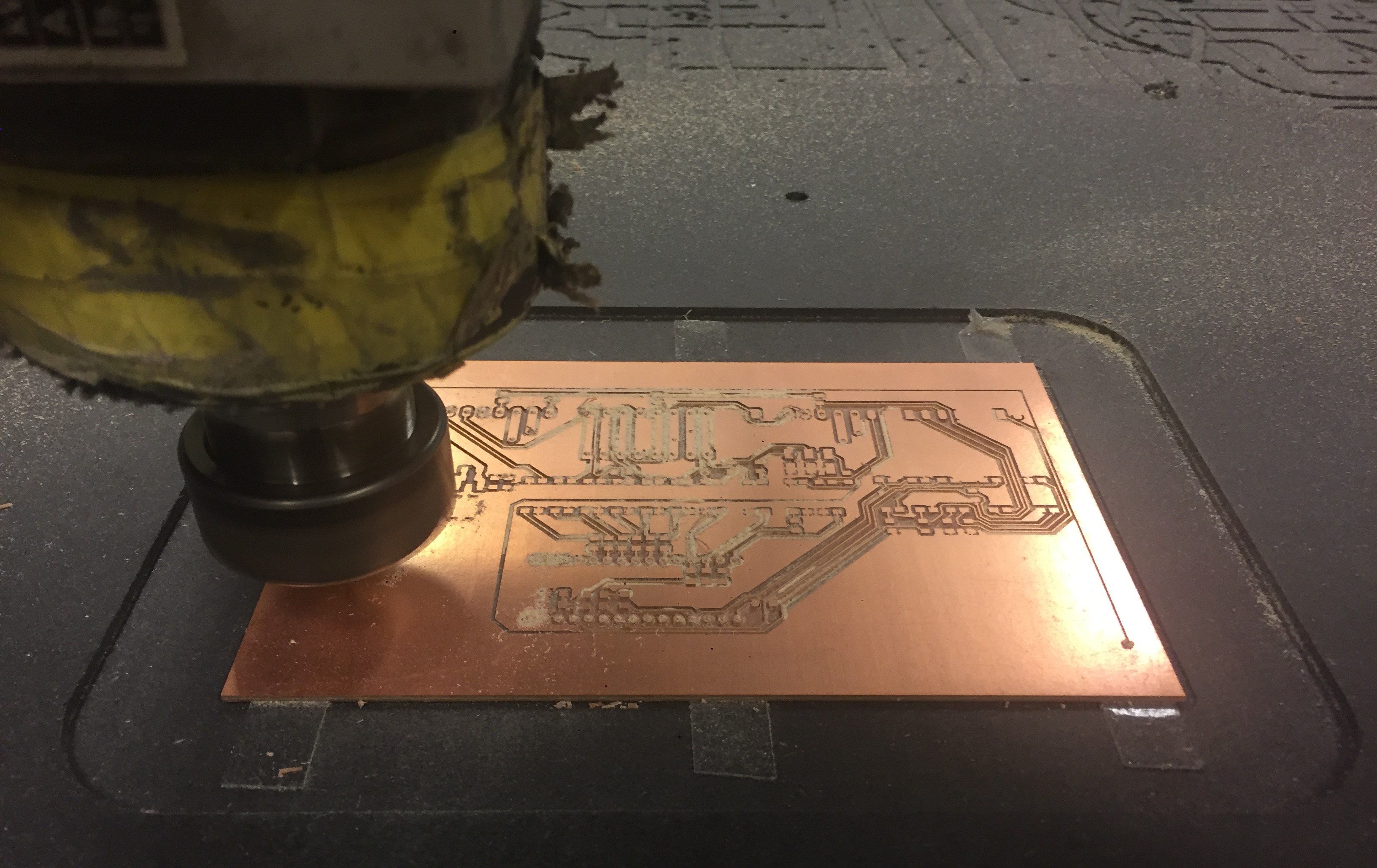
- Low backlash (unfortunately not yet measured, but see photo of PCB milling bellow for reference)
- High enough accuracy for most tasks so far
- Scales well. Can be used on small machines and giant machines and there is no increase of elasticity the longer you make your axes. This is the same for all rack and pinion types. (unlike belts and lead/ballscrews)
- No calibration of travel distance per motor revolution needed, and very little accumulated error or in positioning. This is the same for all rack and pinion types. (unlike the need to measure degree of timing belt stretch)
- Integrating the rack in the same part that provides rails and structural strength is sexy. Modular racks are great too.
- Set screws work when we have three of them and M5 size (Only one set screw and M4 was not enough and the pinion straitened slipping when the motor shaft heated up)
- Sufficiently stiff for small machines. But on the Alu version of Humphrey the gantry weighs about 45kg with all motors and spindle. With so much weight the springiness of the steppers is still a problem, and the wear rate of pinions too high. Developing and testing fabricatable gearboxes is in our pipeline. A small early test with a fabricatable strainwave gear on youtube here


These gears are meant for driving rotary axes, gearboxes and more. The files published are meant for our standard 8 tooth pinion on an 8mm Nema23 motor shaft. But you can both scale the files and use the parametric generator in Grasshopper to generate custom gears. We have published gear ratios from 1:2 to 1:20 in both internal and external teeth versions:
- DXF
- SVG
- Rhino and Grasshopper (with parametric generator)


Not yet tested, test feedback welcome

The eccentric bushing makes it possible to fine tune the position of a bearing against a rail. It is a simple 3D printed part and takes 5-10 minutes to print. It is designed not to take any loads from the bearing, but only assist in positioning the screw holding the bearing. Once the nut and screw is tightened, the load is transferred to the large washer on either side of the carriage stock.
Thanks to the large washers that spreads the clamping force, the design permits machines to be made from softer and easier to mill materials than the open builds eccentric nut. The large washers and short distance from stock to bearing also increases rigidity. You only need regular easy to find hardware and it makes for a much cheaper solution than ready made-eccentric stud type track rollers.
It is important to have a snug but not too tight fit inside the milled hole in the carriage. It is also important that your screw can self-tap in the bushing. So you might need to adjust the tolerances in the parametric Freecad file to find the optimal parameters matching your 3D printer. Use a wrench or pliers to hold the flats when screwing. Don't forget to add the bearing, a small washer and a large washer to the screw before you screw on the eccentric bushing.
BOM per bearing: 1 3D printed eccentric nut, 1 hex head machine screw, 2 large washers, 1 small washer and 1 nut.
- STL (for replacing KRE16 track rollers on Wooden Humphrey with M5 machine screws and 16mm bearings)
- STEP (for replacing KRE16 track rollers on Wooden Humphrey with M5 machine screws and 16mm bearings)
- Freecad (with parametric generator)
- Freecad assembly for illustration (cross section)


This is a KRE16 stud type that the eccentric bushing is meant be low cost and lower perforce alternative to
This is early work in progress. The files can be found here. The goal of is facilitate the building of custom machines with only traditional wood working equipment for the instances where someone does not have access to a large format milling machine.

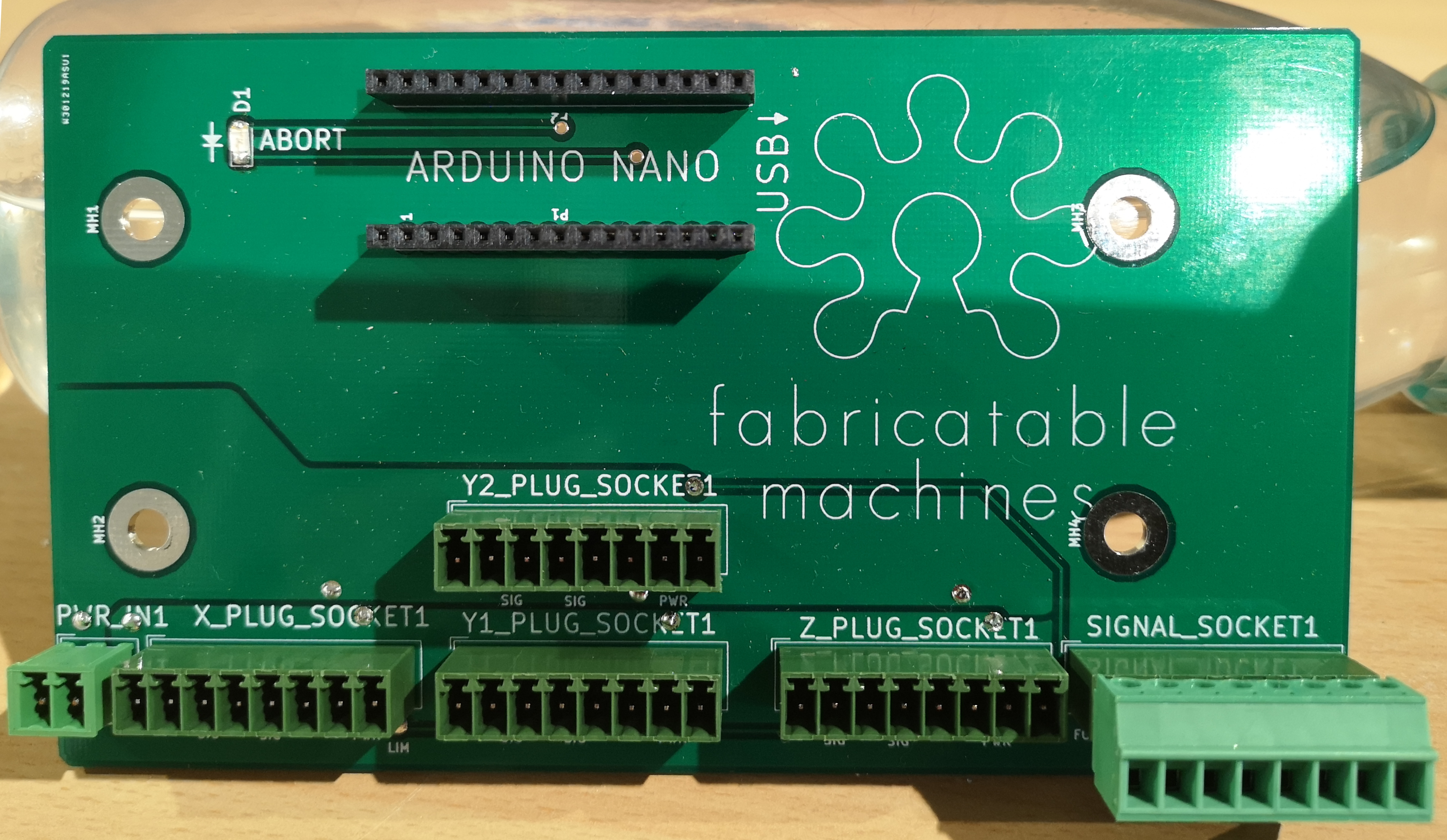
The HRBL-shield makes it fast and easy to wire up favorite integrated closed loop stepper motors. It designed to be bot easy to CNC mill yourself or order ready-made from a boardhouse.

Files here


