ATF Circuit Editor Sample

CircuitEditor is a sample editor for circuits, consisting of modules with input and output pins and connections between them. It uses an XML Schema to define the data file format, reads and writes XML circuit files, and allows circuits to be edited using a graphical representation of modules and connections. It uses the AdaptableControl to display and edit the circuit. Multiple documents can be edited simultaneously. CircuitEditor uses several ATF Editor components to implement standard editing commands. CircuitEditor also demonstrates:
- Prototyping: you can create a custom set of circuit fragments that can be inserted into documents.
- Layering: you can assign diagram components to layers that can be turned on and off (visible and invisible).
- Circuit Groups and Circuit Templates.
- Define a data model using a Circuit.xsd XML schema.
- Use of DOM to store a data model in memory.
- Use of adapters to decorate the DOM to create a Circuit data model.
- Use of ContextRegistry to track the active editing context, so application components always apply where the user is editing.
- Use of AdaptableControl to display and edit circuits using graph abstractions.
- Use of TransformAdapter, CanvasAdapter, and ViewingAdapter to implement the Circuit canvas.
- Use of ScrollbarAdapter, AutoTranslateAdapter, MouseTransformManipulator, and MouseWheelManipulator to allow the user to pan and zoom the Circuit canvas.
- Use of D2dGraphAdapter, D2dGraphNodeEditAdapter, and D2dGraphEdgeEditAdapter to display and allow editing of circuit modules and connections.
- Use of HoverAdapter to display information when the mouse hovers over circuit module items.
- Use of D2dAnnotationAdapter to display annotations and edit their text on the canvas.
- How to use the global (Windows®) clipboard, so that users can copy/paste into other ATF circuit diagram editor samples.
- Use of PropertyEditor and GridPropertyEditor components to edit properties in list and grid property controls.
- Circuit Groups and Circuit Templates, which are described here.
- Editor.cs implements IDocumentClient and uses document framework to manage multiple documents. It implements File menu commands, auto-new and open documents on startup.
- ModulePlugin.cs shows how to implement IPaletteClient and uses IPaletteService to create the Circuit Module parts palette.
- PrototypingContext.cs shows how to implement IPrototypingContext and uses the PrototypeLister component to allow prototyping.
- LayeringContext.cs shows how to implement ILayeringContext and uses the LayerLister component to allow editing and showing/hiding layers.
- GroupingCommands.cs shows how to implement group/ungroup commands: replace selected modules with a single module that contains the original modules and preserves all connections and the reverse process.
- Double-click the CircuitEditor.exe in \bin\wws_atf\Release.
- The CircuitEditor window appears.
- You can open a sample file data\Example.circuit in the CircuitEditor project files.
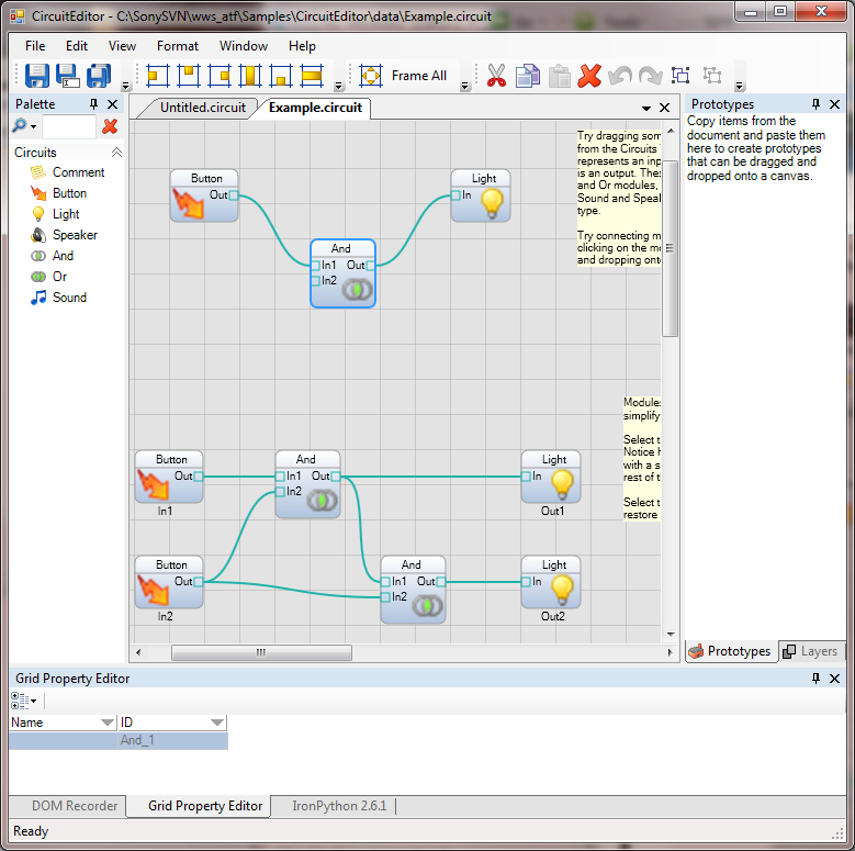
CircuitEditor has the following panes:
- Palette (Circuit Modules): the Circuit parts palette: Comment, Button, Light, Speaker, And, Or, and Sound.
- Canvas: define, view, and edit circuits.
- Property Editor: edit the selected module's property in a list control.
- Grid Property Editor: edit the selected module's property in a grid control.
- Prototypes: lists the custom Circuit fragments that you define for use in your circuits.
- Layers: list layers and their circuit modules.
The menu bar contains:
- File: create a new circuit, open an existing circuit, Save, Save As, Save All, Close, Recent Files, and Exit CircuitEditor.
- Edit: in addition to the standard editing functions (Cut, Copy, Paste, Undo/Redo, and so on), Edit provides:
- Selection: Select All, Deselect All, Invert Selection.
- Group/Ungroup: create/disassemble a circuit module group.
- Keyboard Shortcuts: use the Customize Keyboard Shortcuts window to set up keyboard shortcuts.
- Load or Save Settings: use the Load and Save Settings window to save current CircuitEditor application settings, or to load application settings from a file.
- Preferences: set application and document preferences, such as command icon size and auto-load the last active documents.
- View: choose Frame Selection or Frame All.
- Format: determine the alignment and size of state elements.
- Window: set layouts, choose pane tiling, and show and hide panes.
- Help: display About dialog describing the application.
CircuitEditor opens with an empty canvas grid.
Create a circuit:
- Drag and drop circuit module elements from the Palette onto the grid.
- Select and drag modules to position them on the grid.
- Pan around the canvas by holding down the Alt key and left mouse button and drag on the canvas.
- Zoom in and out by pressing Alt key while rotating the mouse wheel.
- Position the cursor at the edge of one module near an Out pin until the cursor becomes an up-arrow.
- Drag to another module until the cursor again becomes and up-arrow near an In pin and then release the left mouse button. Note that only appropriate destination elements are displayed while you are dragging; the others are "whited out".
- Click the left mouse button on the Out pin.
- Click again on the destination In pin.
Select elements several ways:
- Click an item to select it.
- Shift+click adds an element to the selection.
- Add/remove items to/from the selection by Ctrl+click.
- Drag a rectangle around a set of elements to select them.
- Change the selection with the arrow keys. This also scrolls the selection into view.
- Select an element to view its properties.
- Change properties in either the list view or grid property editor.
- Select the circuit module(s) to include in the layer.
- Copy the selected circuit module(s) to the clipboard.
- Paste the circuit module(s) in the Layers pane.
- Click the "New Layer" field and enter the name you want for the layer.
To create a group:
- Select the circuit modules to be grouped.
- Select either Edit > Group, or click the Group button on the toolbar.
To ungroup elements:
- Select the group.
- Click the Ungroup button on the toolbar.
- Select circuit elements including group(s).
- Paste into the prototype pane.
- Click the "Prototypes" label and enter the name of the prototype.
- Drag prototypes onto the canvas to instantiate new elements from the prototype.

- Home
- Getting Started
- Features & Benefits
- Requirements & Dependencies
- Gallery
- Technology & Samples
- Adoption
- News
- Release Notes
- ATF Community
- Searching Documentation
- Using Documentation
- Videos
- Tutorials
- How To
- Programmer's Guide
- Reference
- Code Samples
- Documentation Files
© 2014-2015, Sony Computer Entertainment America LLC