-
Notifications
You must be signed in to change notification settings - Fork 0
PCB Defect Detection on RZBoard V2L
High accuracy detection of short circuits, open circuits, and missing holes with < 6 watts.

Difficulty: Intermediate
- Hands-on Estimate: 2 hours
- Real-Time PCB Defect Detection on RZBoard V2L
Before you begin, make sure you have the following hardware and software in place:
- RzBoard V2L
- 1x FHD USB Webcam (I'm using DEPSTECH D04)
- USB-Serial adapter cable (I'm using PL2303TA)
- 1x ethernet cable
This blog post is an extention/fork of Solomon's blog post for the raspberry pi!
This blog assumes the reader is running an RZBoard V2L with a BSP from VLP 3.0.2 or 3.0.4 (two most recent official releases of RZBoard BSP at this time), but any BSP containing NPM/Node should do.
Want to use pre-built images? Check out the 'Reference Design' tab of the V2L product page
The global PCB market is anticipated to grow aggressively, reaching $104.8 billion by 2033. How will companies grow rapidly while maintaining quality standards? Automated defect detection can help scale manufacturing by detecting issues quickly and sifting products as necessary.
When looking to automate defect detection, there is a massive variety of sensor and device options. It can be difficult or expensive to know if a certain sensor, device, or model will work well in production. Several prototypes may be needed before deciding upon a solution. This blog uses Edge Impulse to help understand model capabilities before deploying and develop protoypes rapidly to the edge.
This project is an extention of Solomon's blog targeted at Raspberry Pi deployement. First, well train a high accuracy defect detection model; then, we will deploy to a device capable of real-time production AI: RZBoard V2L. RZBoard can easily run various real-time computer vision models and supports USB and MIPI camera interfaces, all in a low power device. Additionally, because RZBoard hands off AI processing to the DRP-AI accelerator, the ARM CPUs can focus on other required processing.
Even if your end goal isn't PCB defect detection, you may find this blog insightful to the capabilities of RZBoard and Edge Impulse. It's very easy to transfer learn object detection or classification models to your domain and then deploy a solution to RZBoard.
Before gathering data or training models, we should establish application requirements and/or expectations. After all, PCB defects come in many forms, and manufacturing requirements are company specific. Some sensible requirements that should be relatable to manufactures are:
- Real time application capabilities (15+ FPS from end to end)
- Model capable of detecting short circuits, open circuits, and missing holes
- Model accuracy above 50% on the test set
Additionally, we expect our trained models to be easily exported to the edge. Thankfully, Edge Impulse provides several formats suitable for customized solutions or quick testing. Examples will be covered in the final sections of this blog.
Be prepared for the most conveniant data gethering of all time...
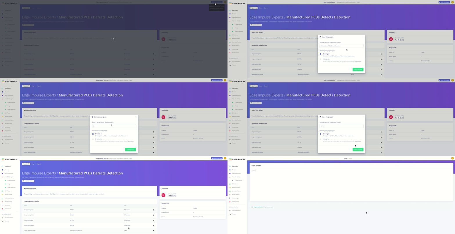
Visit this public project link and clone the project for yourself with a button click.
Once that job is done, you are ready to select your target device and take a look at the provided datasets. Make sure to select the RZV2L with DRP-AI acceleration!
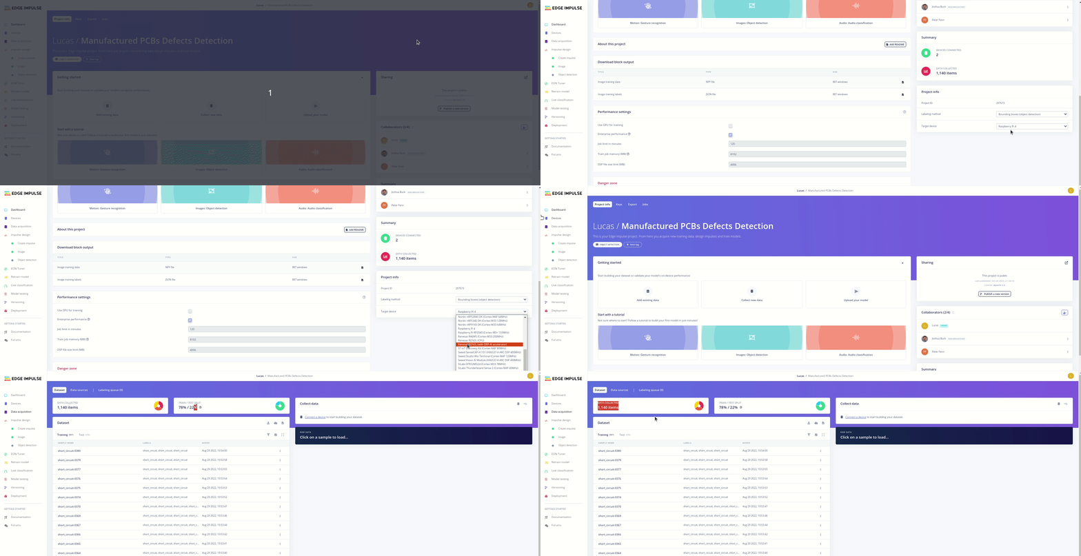
Thankfully, labeled train and test sets have been provided- we get to spend our time iterating impulse designs.
Knowing our requirements and having our data gathered, we are prepared to begin training! If you're unfamiliar with Edge Impulse, this is known as impulse design.
The newest problem is: what model is optimal for RZBoard with the available Edge Impulse compute? While there are several hints to put us on the right path, finding our model and training parameters will be an iterative process.
The following sections will cover my training experiences so you can build off of them yourself!
The "Create Impulse" tab is the beginnining of model training. Essentially, you start by designing a block diagram of your model: input, learning, and output blocks.
I will be varying model input with different training sessions; however, the learning and output blocks will remain constant. You shouldn't have to change those values from the cloned impulse design. The learning block will remain object detection, and the processing block will remain as 3 output features: missing hole, open circuit, and short circuit.
The first model I train will be 320x320 input size; input that size and click "Save Impulse" on the left side of your screen.
The Image tab is for defining your model input space and generating features. The first model I train will be RGB. Go ahead and select RGB, save parameters, and then generate features.
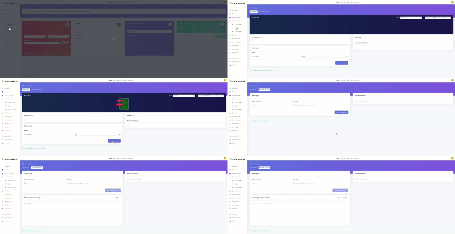
Moving forward, I will be selecting different models and hyperparameters in the "Object Detection" tab.
Having worked with YOLO before on defect detection, the first model I trained was a YOLOv5 model. With a 320x320 RGB model input, I selected 50 training cycles and 0.002 learning rate.
I kicked off model training with the Start Training button, selected the notification bell in the top right for emails, and came back to the following model training results:
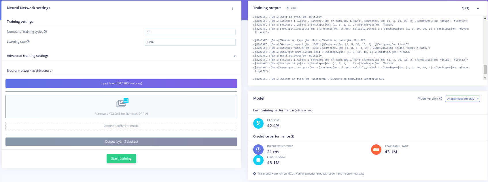
An F1 score of 42.4% is not too bad for the first model trained! 42% is obviously better than baseline. Exciting, we're getting meaningful results!
What about the rest of the model performance? 21 ms inference time -> ~47 FPS... Okay that would be great if true! Ofcourse, there would be all sorts of processing happening at runtime besides inference, but we can definitely work with this inference time. Lets see if we can get a more accurate model.
Solomon gets 48% on his first model trained, can we beat that? His first model trained is FOMO grayscale at 1024x1024 image size. My intuition tells me that image size is quite large for several reasons. Generally, model complexity scales model training complexity (training time, dataset size, iteration speed). Thankfully, Edge Impulse is giving us foundational models to transfer learn off of, allowing us to use smaller datasets. Still, this image size is quite large for training and edge device deployment.
I'll opt to train 320x320 grayscale and see what happens. Model hyperparemeters: 60 training cyles, 0.002 learning rate, data augmentation enabled. I kicked off the model and returned to the following:
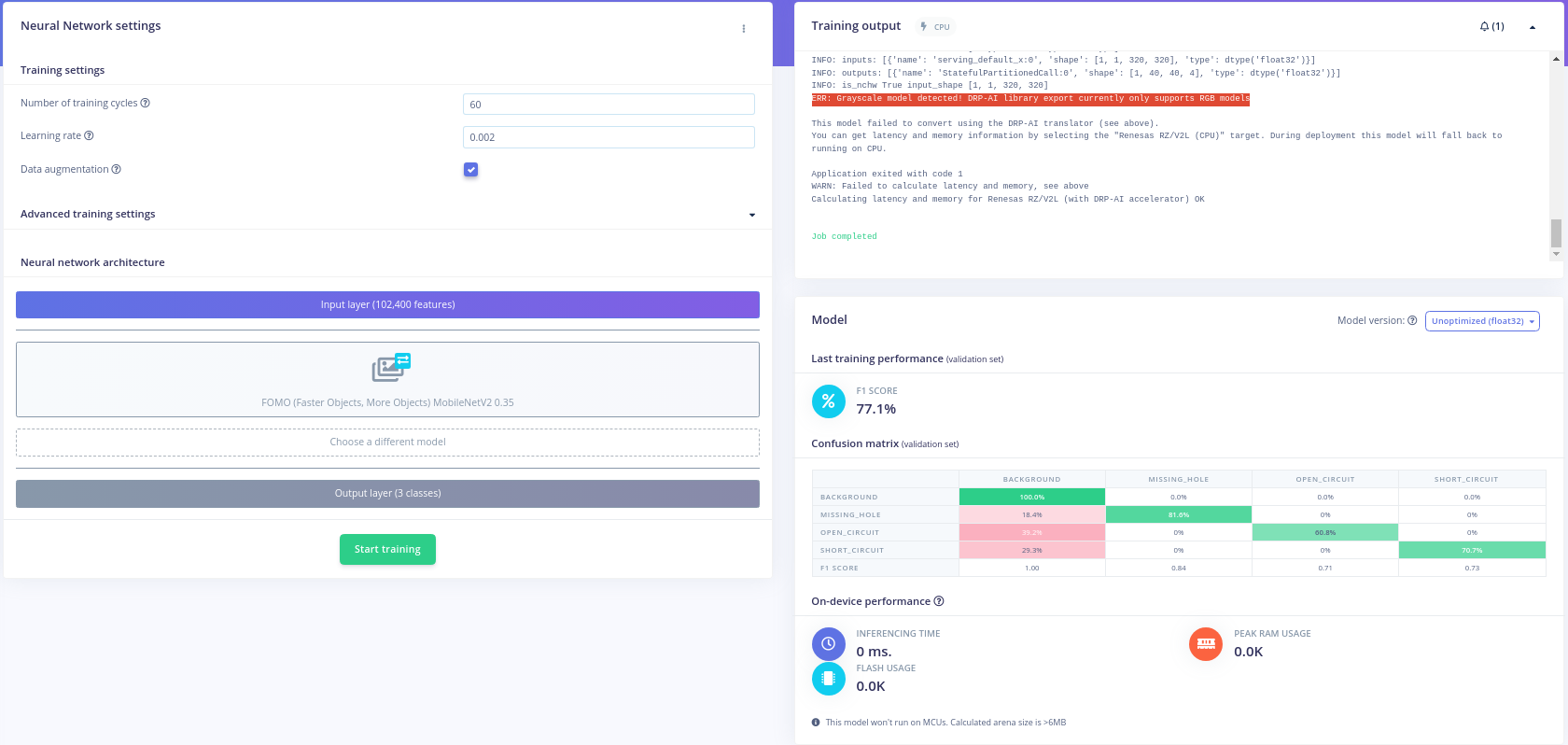
Wow! 77% F1 score is significantly better! Honestly, its incredible we can get this sort of model training so quickly.
What is up with the on-device performance metrics? Instantaenous training time? Unlimited power?! No. Unfortunately, digging into this error more (on edge impulse and DRP AI documentation), I've realized a limitation we must work around when iterating- currently, the DRP-AI engine only supports RGB format images.
Understanding this model cant be deployed to DRP-AI, we have a new target of 77% F1 score with RGB model input!
Naturally, using FOMO to reach 77% seemed like a good idea. I updated my model input to become 290x290 RGB and went back to the FOMO training tab. Selecting 60 training cycles and 0.002 learning rate, I kicked off a new model.
Wondering why I have this pattern of model hyperperameters? Simple answer: I don't have a professional Edge Impulse account, so I'm restricted on training times.
Anyway, an email came in notifying me of the following model results:
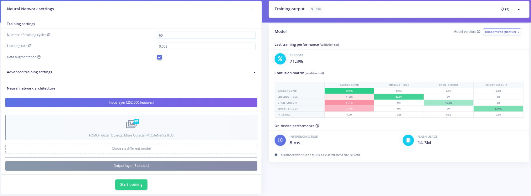
71% F1 score with 8 ms inference time? This looks promising! We didn't achieve the 77%, but we could certainly try with increased training times & some tuning of model input. This seems to imply higher image resolution is a better predictor of model performance than more color channels for our application, but its obviously very early to be confident of that.
How do other models compare? Edge Impulse also provides Mobilenet SSD, we should give it a try! Edge Impulse does note that FOMO was designed for a small footprint object detection that performs well for many, small objects, so FOMO is expected to perform better than Mobilenet SSD for our use case.
The pretrained Mobilenet models expect model input size 320x320, so I updated my model input for 320x320 RGB. Lastly, I selected 35 training cycles and 0.015 learning rate at Edge Impulse's recommendation. I kicked off my model training and came back to the following results:
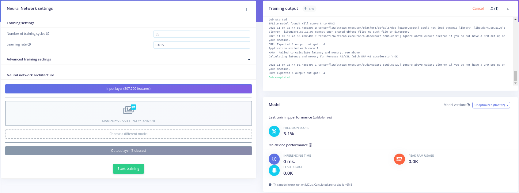
Wow! Surprisingly bad model performance; not much to talk about here. I tried a few more training configurations, but the results were poor so I moved on.
Of the displayed training results, its clear FOMO is performing better than its competitors. Specifically, the 290x290 RGB 60 epoch model results are great. I'm going to stick with a FOMO architecture and train one last model or two to see if I can get those confusion matrix numbers up!
Because our defects are quite small portions of the image, I'm going to try bumping up the model resolution, but not quite as high as Solomon did. I kicked off a 500x500 RGB model with 50 training cycles at 0.002 learning rate, and look at the results!

Incredible- 88.1% F1 score. A far better model than anything trained so far. Model input size seems a significant factor of performance given our current compute and dataset.
At this point, I knew it was time to begin model testing and deployment with the FOMO model.
Model testing on Edge Impulse is painless if you already have a holdout set. Thankfully, this work has been done for us by Solomon and the PCB dataset authors. To test model performance of the FOMO model, I simply started a classify job with the "Classify all" button at the top of the "Model Testing" page.
The results came back for analysis. Lets start by looking at the test graph.
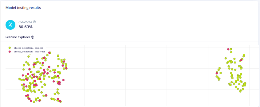
80.63% accuracy on our test set. What does that mean? In this case, Edge Impulse has defined accuracy as The percentage of all samples with precision score above 80%, as seen from hovering over the "?" icon. At first sight, this number is relatively impressive, but how can this be interpreted?
WAIT! For the use case of defect filtering or MTBF analysis, identifying a single defect on a board is sufficient. This implies that our model could be performing even better than that 80% implies. If we are frequently detecting some, but not all of the defects, that's probably okay.
Looking at the training confusion matrix, and various test set samples, our model appears to have a very high precision- higher than recall. In other words, you can trust our model when it has found a defect, but some defects are not being detected. This seems to imply our 80% accuracy is even better than it looks, as long as you're okay with detecting some, but not all defects.
Ultimately, it will be up to manufacturers to define what is most important to them: precision or recall; however, it's been demonstrated training and testing on Edge Impulse can quickly yield impressive results.
Now, lets deploy the model for on-board testing with RZBoard V2L.
Edge Impulse offers several ways to deploy models. This blog will focus on methods 1) Deploy as a customizable library and 2) Deploy as a pre-built firmware - for fully supported development boards.
In this section, I'll detail deploying the FOMO model as a C++ SDK. This solution offers boilerplate to build performant application code around DRP-AI and model weights. If you want to see immediate model testing, visit the Deploy as a Pre-Built Firmware section.
Firstly, deploying as a customizable c++ library is as simple as visiting the "Deployment" tab and kicking off a "C++ library" deployment job.
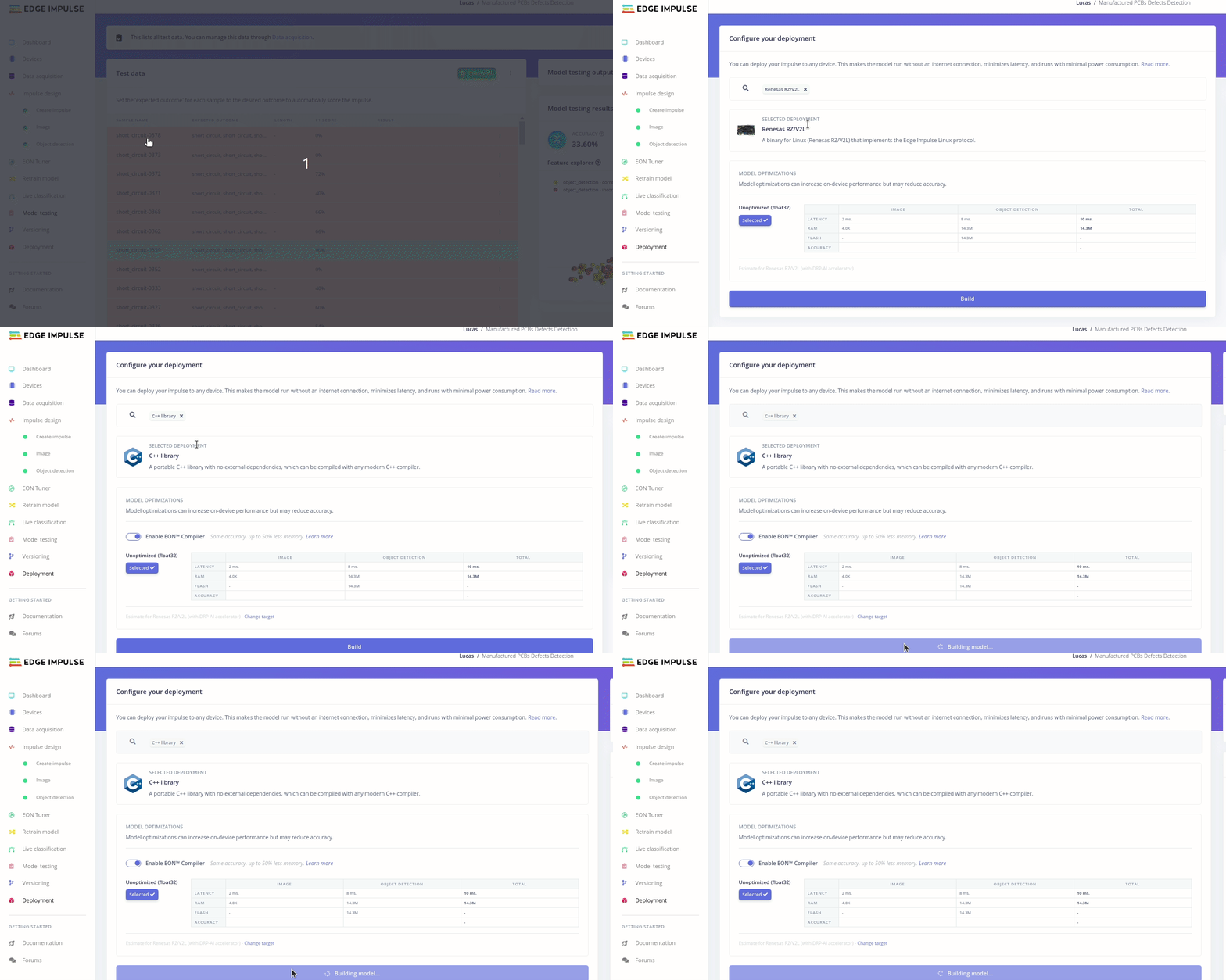
Once your job is done, you'll get a deployment pop up:

Simply click the model in the top right to download it.

Edge impulse has great material on deploying your model as a c++ library. The high level steps to get the model running on the edge are as follows:
- Extract library contents from the zip file
- Create a main.cpp file that utilizes the c++ library
- Update the supplied CMakeLists.txt with your new main file
- Deploy the library to the edge
- Build and execute the main file
Ofcourse, you could cross-compile or create a yocto recipe for the model in production, but we will take the fast approach as all build dependencies exist on the edge. Refer to the Edge Impulse blog material if you get stuck! Below is a high-level step through the process.
Extract the file zip contents into a path of your choice. Verify the conents look something like this:
» tree -L 2
.
├── CMakeLists.txt
├── edge-impulse-sdk
│   ├── classifier
│   ├── cmake
│   ├── CMSIS
│   ├── dsp
│   ├── LICENSE
│   ├── LICENSE-apache-2.0.txt
│   ├── porting
│   ├── README.md
│   ├── sources.txt
│   ├── tensorflow
│   └── third_party
├── model-parameters
│   ├── model_metadata.h
│   └── model_variables.h
└── tflite-model
    └── drpai_model.h

13 directories, 12 files
Create the main.cpp file at the library root.
touch main.cpp
Copy the following file contents:
#include <stdio.h>

#include "edge-impulse-sdk/classifier/ei_run_classifier.h"

// Callback function declaration
static int get_signal_data(size_t offset, size_t length, float *out_ptr);

// Raw features copied from test sample (Edge Impulse > Model testing)
static float input_buf[] = {
};

int main(int argc, char **argv) {

    signal_t signal;            // Wrapper for raw input buffer
    ei_impulse_result_t result; // Used to store inference output
    EI_IMPULSE_ERROR res;       // Return code from inference

    // Calculate the length of the buffer
    size_t buf_len = sizeof(input_buf) / sizeof(input_buf[0]);

    // Make sure that the length of the buffer matches expected input length
    if (buf_len != EI_CLASSIFIER_DSP_INPUT_FRAME_SIZE) {
        printf("ERROR: The size of the input buffer is not correct.\r\n");
        printf("Expected %d items, but got %d\r\n",
                EI_CLASSIFIER_DSP_INPUT_FRAME_SIZE,
                (int)buf_len);
        return 1;
    }

    // Assign callback function to fill buffer used for preprocessing/inference
    signal.total_length = EI_CLASSIFIER_DSP_INPUT_FRAME_SIZE;
    signal.get_data = &get_signal_data;

    // Perform DSP pre-processing and inference
    res = run_classifier(&signal, &result, false);

    // Print return code and how long it took to perform inference
    printf("run_classifier returned: %d\r\n", res);
    printf("Timing: DSP %d ms, inference %d ms, anomaly %d ms\r\n",
            result.timing.dsp,
            result.timing.classification,
            result.timing.anomaly);

    // Print the prediction results (object detection)
#if EI_CLASSIFIER_OBJECT_DETECTION == 1
    printf("Object detection bounding boxes:\r\n");
    for (uint32_t i = 0; i < EI_CLASSIFIER_OBJECT_DETECTION_COUNT; i++) {
        ei_impulse_result_bounding_box_t bb = result.bounding_boxes[i];
        if (bb.value == 0) {
            continue;
        }
        printf("  %s (%f) [ x: %u, y: %u, width: %u, height: %u ]\r\n",
                bb.label,
                bb.value,
                bb.x,
                bb.y,
                bb.width,
                bb.height);
    }

    // Print the prediction results (classification)
#else
    printf("Predictions:\r\n");
    for (uint16_t i = 0; i < EI_CLASSIFIER_LABEL_COUNT; i++) {
        printf("  %s: ", ei_classifier_inferencing_categories[i]);
        printf("%.5f\r\n", result.classification[i].value);
    }
#endif

    // Print anomaly result (if it exists)
#if EI_CLASSIFIER_HAS_ANOMALY == 1
    printf("Anomaly prediction: %.3f\r\n", result.anomaly);
#endif

    return 0;
}

// Callback: fill a section of the out_ptr buffer when requested
static int get_signal_data(size_t offset, size_t length, float *out_ptr) {
    for (size_t i = 0; i < length; i++) {
        out_ptr[i] = (input_buf + offset)[i];
    }

    return EIDSP_OK;
}
Notice this application expects a sample in the form of a raw data buffer to perform inference upon. Thus, we must pick a sample with known model output results, download the raw sample data, paste that into our main file, and compare the Edge Impulse inference results with our local results to ensure the library is functioning properly. Lets do that!
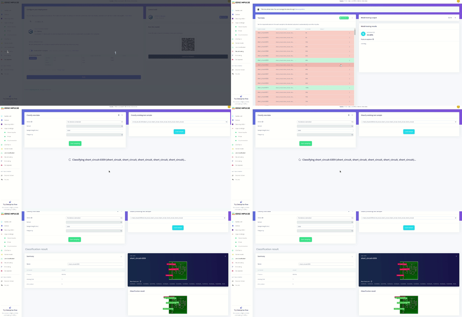
Warning: Dont forget to paste that raw data buffer into
static float input_buf[] = {}of the main file!
Now, we just have to get our main compiled and deployed to our RZBoard!
Update the CMakeLists.txt to look like the following:
cmake_minimum_required(VERSION 3.13.1)

Project(app)

add_executable(app
main.cpp)

if(NOT TARGET app)
     message(FATAL_ERROR "Please create a target named 'app' (ex: add_executable(app)) before adding this file")
endif()

include(edge-impulse-sdk/cmake/utils.cmake)
add_subdirectory(edge-impulse-sdk/cmake/zephyr)

RECURSIVE_FIND_FILE_APPEND(MODEL_SOURCE "tflite-model" "*.cpp")
target_include_directories(app PRIVATE .)

# add all sources to the project
target_sources(app PRIVATE ${MODEL_SOURCE})
SCP the library to your RZBoard. Go to the library directory.
Make a build directory and begin compiling the source (this will take some time on RZBoard).
root@rzboard:/defect-detection# ls
CMakeLists.txt  edge-impulse-sdk  main.cpp  model-parameters  tflite-model
root@rzboard:/defect-detection# mkdir build
root@rzboard:/defect-detection# cd build/
root@rzboard:/defect-detection/build# ls
root@rzboard:/defect-detection/build# cmake ..
-- The C compiler identification is GNU 9.3.0
-- The CXX compiler identification is GNU 9.3.0
-- Check for working C compiler: /usr/bin/cc
-- Check for working C compiler: /usr/bin/cc -- works
-- Detecting C compiler ABI info
-- Detecting C compiler ABI info - done
-- Detecting C compile features
-- Detecting C compile features - done
-- Check for working CXX compiler: /usr/bin/c++
-- Check for working CXX compiler: /usr/bin/c++ -- works
-- Detecting CXX compiler ABI info
-- Detecting CXX compiler ABI info - done
-- Detecting CXX compile features
-- Detecting CXX compile features - done
-- Configuring done
-- Generating done
-- Build files have been written to: /defect-detection/build
root@rzboard:/defect-detection/build# make
...
Lastly, run the source and validate the results against your Edge Impulse sample!
$ ./app
run_classifier returned: 0
Timing: DSP 12 ms, inference 0 ms, anomaly 0 ms
Object detection bounding boxes:
  missing_hole (0.852539) [ x: 63, y: 42, width: 7, height: 7 ]
  short_circuit (0.978027) [ x: 63, y: 49, width: 7, height: 7 ]
  short_circuit (0.978027) [ x: 91, y: 56, width: 7, height: 7 ]
  short_circuit (0.949219) [ x: 126, y: 112, width: 7, height: 14 ]
  short_circuit (0.976074) [ x: 91, y: 119, width: 7, height: 14 ]
  short_circuit (0.918457) [ x: 49, y: 203, width: 7, height: 14 ]
Edge Impulse close up:
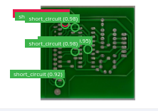
Great, this model correctly finds all short circuits and erroneously detects a missing hole! The results & confidence scores are just as expected for this sample. The displayed performance numbers are from one of my smaller models (before finding success with bigger models), but the values you see in logs should link against the predicted values form Edge Impulse. Production solutions would now begin building up the application around this library.
However, if you want to see a solution integrated with camera backends and a webserver, check out the Deploy as a Pre-Built Firmware section!
Lastly, I'll describe deploying the FOMO model and firmware through the edge impulse CLI. This solution grants a rapid way to demo model performance on the edge, automatically making use of DRP-AI and camera peripherals.
Connect RZBoard to the internet and establish a shell connection. Send the following command:
npm config set user root && npm install edge-impulse-linux -g --unsafe-perm
With the RZBoard node dependencies setup, and a camera connected, run the following command:
edge-impulse-linux-runner
Step through the command prompt as necessary. Eventually, this command will prompt edge impulse servers to package and deploy our model to the edge for inference. Additionally, the final application will automatically look for cameras and start inferencing! Very convenient for rapid prototyping. The log output is packed with relevant information, make sure to read it.
You should see a pop-up about viewing the camera feed through a web browser. Visit that link in a LAN browswer to see the model running inference in real time! Here is an example of my local runner and a perfectly good PCB:
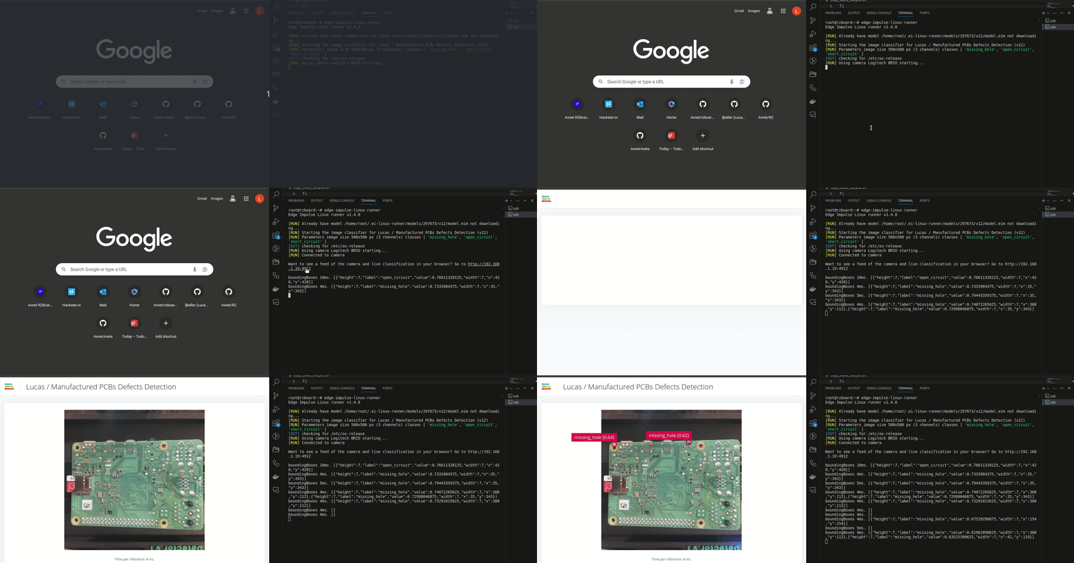
The 3D-Printed stand to emulate overhead view:
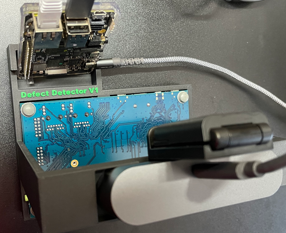
I don't expect this synthetic dataset to carry over very well to noisy, real-life data, but perhaps some domain adaption could bootstrap a production solution! Or, ofcourse, just add upload your data to Edge Impulse for transfer learning.
In practice, a model with higher resolution input, domain-specific data, and longer training times should yield even better results! Still, this model satisfies all of our original requirements and the model pipeline was quick to iterate upon. What more can you ask for!? I'm just glad I'm not spending countless hours fiddling with Nvidia Drivers :). I hope you found this blog demonstrative of RZBoard/Edge Impulse ML capabilities!
We welcome feedback, bug reports, and contributions. If you encounter any issues or have suggestions for improvements, please feel free to open an issue, or leave comments below!