-
Notifications
You must be signed in to change notification settings - Fork 23
QuantoDerive
QuantoDerive is the new scala-based GUI that will replace the existing Quantomatic GUI. These pages are for planning various aspects of the tool. QuantoDerive uses a project-based idiom for defining systems of axioms and using axioms to perform derivations. A project consists of various JSON files:
-
main.qtheory- details about how a particular theory is visualised and implemented in the core -
*.qaxiom- axioms. Rules that do not need to be proven. -
*.qgraph- graphs. These can be edited and used to start derivations. -
*.qderive- derivations. Conceptually, these are trees, where nodes correspond to a single application of a rewrite rule. -
*.qtheorem- theorems. Rules whose validity needs to be established. This is done by tagging proof heads in derivations with a theorem's name.
For more info on graph, rule, and theory formats, see file formats.
Following the project/IDE style, the (directory or logical) structure of the project is displayed on the side, with a main editing area in the centre. Theories can be modified using three distinct modes of editing, which are activated depending on what kind of file is in focus. The three modes of editing are as follows.
- Graph Editor - for auxiliary and scratch graphs
- Rule Editor - for axioms and theorems
- Derivation Editor - for derivations
A central concept in QuantoDerive is that of validation. For a theorem to be valid, it must be connected to a valid derivation. For a derivation to be valid, every step must be an axiom or another valid theorem. Thus, the validity of one theorem can depend on the validity of another. Clearly this dependency relation must be well-founded, with the bottom elements all axioms. More details are given below.
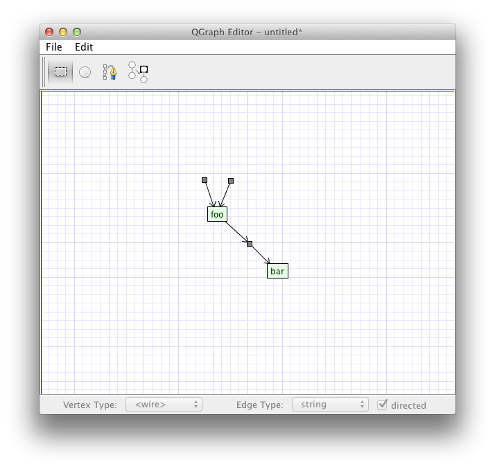
The graph editor can be run stand-alone or (ultimately) inside of QuantoDerive. Its designed to be as simple as possible, and does not need to communicate with the core. It loads and saves files in the .qgraph file format.

Many aspects of the interface are obvious, so here are suggestions on how to do the less obvious things.
Currently, all vertices are laid out with fixed positions. However, it might be nicer to only give fixed positions for node-vertices and boundaries (i.e. wire-vertices with one or zero adjacent edges), then lay out the intermediate nodes automatically. For multiple wires between two node-vertices, it would look nice to lay out wire-vertices interpolated along the bezier curve of each edge.

The intermediate wire-vertices should be selectable, but not draggable. Deleting a wire-vertex would upgrade its neighbour(s) to boundaries.
!-boxes are add via the Add !-Box tool. With this tool selected, the user can drag boxes around collections of vertices to ! them. They can also be modified when the Select tool is active (TODO: decide whether to let !-box editing be its own tool). !-boxes can be edited in various ways. Most of these have to do with working with the "hot corner" of the !-box, which can be thought of as logical !-node which connects to the contents of the box. (See arXiv:1204.6695 for how this works).

Delete a !-box by selecting it and pressing the DELETE key. Add child vertices or !-boxes by dragging a line from the corner of the !-box to the vertex or child !-box. When a !-box is selected, it will show lines connecting the corner of the !-box to any of its child vertices or !-boxes. Centred on each of these lines is a small X the user can click to remove the child from the !-box. The lines and the X'es should be light and unobtrusive (perhaps becoming darker on mouse-over) to not confuse the eye.
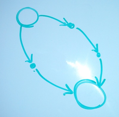
Rules are edited much as before, in a side-by-side manner. One notable difference is that boundaries are visually (and semantically) distinguished from other wire vertices. Boundaries are created by a distinct tool, not available in the graph editor, which creates a boundary in the same physical position on both sides of the rule. The boundary vertices on the LHS and the RHS are then locked to each other, so when the user moves or deletes the boundary on one side, the change occurs simultaneously on the other side.
!-boxes are treated in a similar manner. When they are created/deleted/nested/un-nested, this operation happens jointly. Also, when a boundary vertex is added or removed from a !-box, this happens jointly.
When the user tries to save, the client checks that all other (non-boundary) wire vertices have exactly one input and one output. Otherwise, it will refuse to save.