After making breakout boards for the RFM12B & RFM69 and getting a taste of what those radios can do, I decided I would like to experiment more with Felix Rusu's software. Of particular interest is the software that Felix has created that enables an Arduino based device to be reprogrammed remotely and wirelessly**. Now I could just buy a few of Felix's fine Moteinos, but I already have a bunch of Unos, Minis, Pro Micros and such. So instead I decided to do a new version of the radio breakout board that adds the flash memory chip. While I was at it, I also added the LED on D9 so that code would work too.
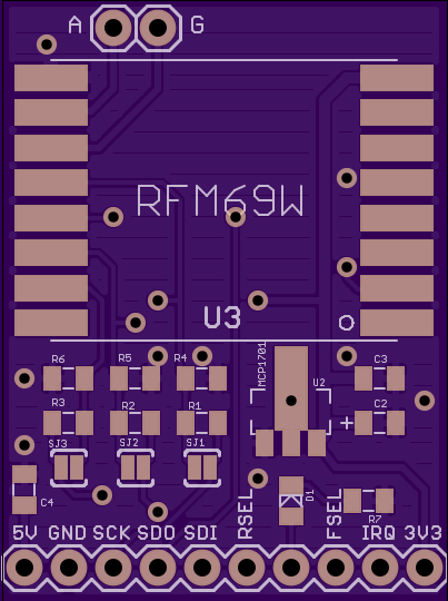
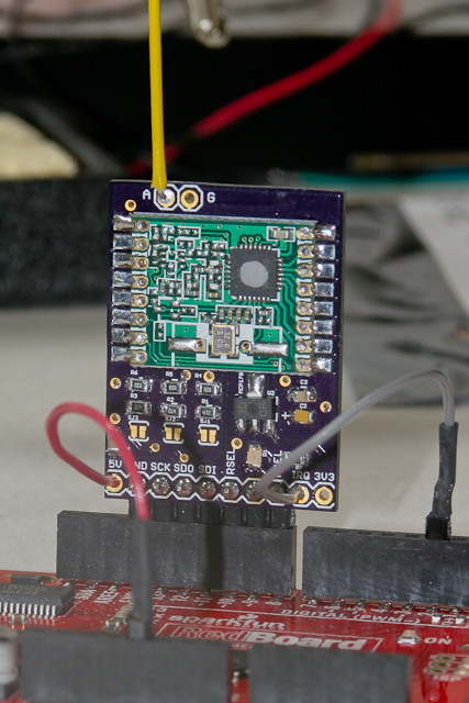
I call the board a half-shield. That is because it will plug directly into an UNO header (plus a couple of wires) but takes up only half the pins.
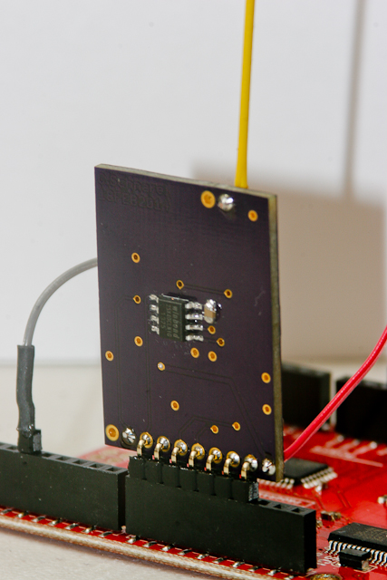
Here is the Moteino Peripherals Half-Shield plugged into an Arduino clone, the RedBoard from SparkFun.
This repo includes Eagle CAD PCB design files for the board. The board converts the RFM69W radio transceiver from SMT to 0.1" breadboard format and provides [optional] level translation for use with 5V controllers. Note that you cannot solder the RFM12B or the RFM69CW radio modules to this board. Use the RFM69W or RFM69HW modules instead.
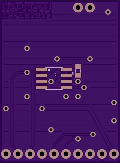
The board also has provision on the bottom side for a conforming SOIC-8 package flash memory part such as the Winbond W25X40CLSNIG.
See the following links for Arduino drivers for the RFM69W and flash memory
Hookup of the breakout board to 5V Arduino SPI connection. All board components populated. Solder-jumpers left open.
Arduino			Half-Shield
  5V	-->		  5V
  GND	<-->	  GND
  D13	-->		  SCK
  D12	<--		  SDO
  D11	-->		  SDI
  D10	-->		  RSEL
  D9	-->		  LED
  D8	-->		  FSEL
  D2	<--		  IRQ
  		<--		  3V3
Hookup of the breakout board to 3.3V Arduino SPI connection. On PCB populate only radio, flash memory, C1, C2 and C3. Short the pads on the solder-jumpers.
Arduino			Half-Shield
  NC	 		  5V
  GND	<-->	  GND
  D13	-->		  SCK
  D12	<--		  SDO
  D11	-->		  SDI
  D10	-->		  RSEL
  D9	-->		  LED
  D8	-->		  FSEL
  D2	<--		  IRQ
  3.3V	-->		  3V3
You can order this PCB directly from OSH Park. Click on the following link.
- Radio Breakout - http://oshpark.com/shared_projects/AadEx5fd
See Bill of Materials file in repo for parts list.
- PCB layout has been tested to be functional using the Low Power Lab example code for RFM69 and SPIFlash.
Design files are in "CadSoft EAGLE PCB Design Software" .brd and .sch formats.
A free version of the software can be downloaded from www.cadsoftusa.com.
You may use this PCB design however you like but no liability is accepted.
** Arduino wireless reprogramming requires a custom bootloader. Read more about it at http://LowPowerLab.com


