-
Notifications
You must be signed in to change notification settings - Fork 9
Actuators
Apart from sensors that measure things, the Astroplant needs 'actuators' to control things like fans and power LEDs. Actuators are 'outputs', components that set things in motion. Many actuators like motors have a high power demand and can not be directly connected to the pins of a Raspberry Pi. For this we need 'relays' or 'drivers'.
Used in the standard Astroplant to switch fans on or off. Since fans often use motors that run with higher voltages and with higher (irregular) currents, it is a bad idea to connect these directly to the Pi GPIO. Relais come in different types:
- Mechanical relays
- Solid State Relays
In this project we use the Grove Relay, which is the mechanical type.
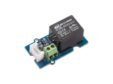
Specs from the manufacturer can be found here. Connect the relay to D16 and adapt one of the scripts that you used to switch a LED in block 1 to switch the relay. You can also look at relay.py. This script will switch the relay on and off.
You can connect a small fan (or a LED) to the relay. Use a red jumper wire to connect the relay with a 5V GPIO pin. Connect the VCC of the fan with the relay. Connect the ground of the relay to a ground GPIO pin. By switching the relay, you will switch the fan. Be carefull: larger fans can cause ugly power spikes on the 5V. It is better to power the fan (or any other device that you want to control) completely separate from the Pi. The Grove Relay can even switch a 220V device, but then be carefull with the high voltage connections.
A nice alternative for 'mechanical' relays are the newer solid state ones. The Grove Optocoupler MOSFET relay is such a device that has no moving parts.(details here...)
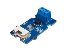
Though this relay can NOT be used for 220V AC it can be used for DC power up to 30V. The nice thing is that it will not 'burn-in' mechanical contacts and can be switched very fast. With PWM it thus is possible to reduce the voltage and make a fan run at slower speeds.
The Grow LEDs in the Astroplant are similar to larger motors in that they use way more power than a Pi GPIO can deliver. As we also want to control the light intensity, we need to dim the bright light down to the right value. An example of a LED driver is the SparkFun FemtoBuck LED driver. (details and hook-up guide)
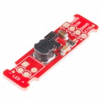
Notice that this driver needs a higher voltage (6-36 Volt to start working). An important thing of LED drivers is that they control the current instead of the voltage. When LEDs get hotter, their resistance drops and so the current would increase further to a point that they burn through.
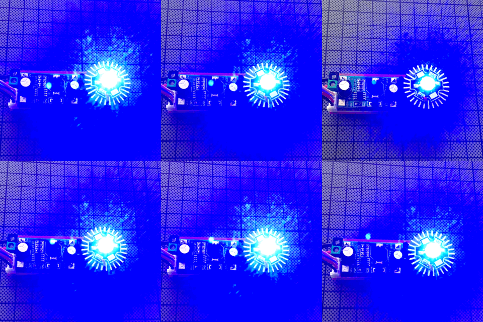
There are also cheaper 1W LED drivers that do work with 5 Volt, like the one used in this little experiment:
To show status and measurements, the Astroplant has a display. The Explorer has a similar display which can be connected to the I2C bus.
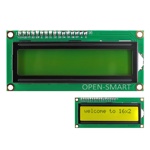
If you installed the AstroPlant software for the sensors, the testscript for the LCD display is already there. (direct link) Make sure you specify the right I2C address. If you do not know the address use the command 'sudo i2cdetect -y 1' to list all i2c devices connected. (you can disconnect the LCD display to see which it is, if you already have more than one)
Basic Learning Stuff
Advanced software
- Overview
- Concepts-and-structure
- Lib
- Demos
Tips-and-Tricks
Future stuff