-
Notifications
You must be signed in to change notification settings - Fork 0
Home
See also: Readme.md
An adder is a basic, well known, VHDL example. With A+B=S, and each vectors coded with N bits, we have :
- <math>S_0=A_0 \oplus B_0 \oplus C_0</math> and <math>C_1=A_0.B_0+A_0.C_0+B_0.C_0</math> with <math>C_0=0</math>
- ...
- <math>S_{N-1}=A_{N-1} \oplus B_{N-1} \oplus C_{N-1}</math> and <math>C_{N}=A_{N-1}.B_{N-1}+A_{N-1}.C_{N-1}+B_{N-1}.C_{N-1}</math> unused
We notice that with A and B coded using two's complement: <math>A-B=A+C_2(B)=A+C_1(B)+1</math>. Adding or subtracting may thus be done by the same silicon with, qualitatively speaking, no drastic increase of silicium use. The previous algorithm is modified to become:
- <math>S_0=A_0 \oplus (B_0 \oplus sub) \oplus C_0</math> and <math>C_1=A_0.B_0+A_0.C_0+(B_0 \oplus sub).C_0</math> with <math>C_0=sub</math>
- ...
- <math>S_{N-1}=A_{N-1} \oplus (B_{N-1} \oplus sub) \oplus C_{N-1}</math> and <math>C_{N}=A_{N-1}.(B_{N-1} \oplus sub)+A_{N-1}.C_{N-1}+B_{N-1}.C_{N-1}</math> unused
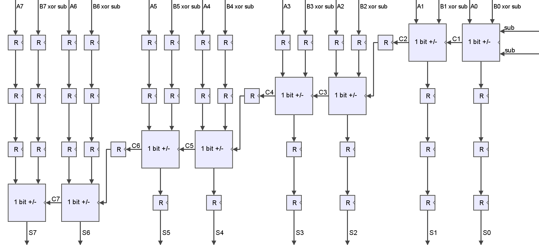
>When A and B are given, the previous description implicitly supposed that the logical function must have ended the calculus before the next clock tick. As the function involves a carry propagation, there is no parallelization between operations and if <math>\tau</math> is the time needed by a 1-bit adder to complete, the entire task will last <math>N.\tau</math>. In order to increase the operating frequency, we can put registers in the design. Indeed, there is a drawback: the calculus latency will increase. But the throughput by clock tick will stay the same (and we will be able to increase the frequency).
This design gives the possibility, with input-ouput vectors coded using <math>N=2^p</math> bits, to place up to p-1 registers in the adder.
The following illustrations were generated using a PHP script embedded in the project.
- 8bits, 0 pipelining level:

- 8bits, 1 pipelining level:

- 8bits, 2 pipelining level:
