[ENH, MRG] Add intracranial electrode localization GUI #9586
Conversation
It should be slightly more general to make this an instance of
Let me know when to look and test! Ideally you would not need to tell me what to do and I can figure it out from the docs/tutorial etc. |
Yeah that's how it is in the code, the comments were a bit out-of-date |
|
|
||
|
|
||
| def test_ieeg_elec_locate_gui_display(): | ||
| mne.gui.locate_ieeg(subject, subjects_dir=subjects_dir) |
There was a problem hiding this comment.
can you micmic clicks ? I suspect this test leads to limited coverage no?
There was a problem hiding this comment.
Yes, hopefully that will be done soon, I've been sorting out the API (e.g. other PR) but this is next
|
Still a work in progress, just for a demo, no need to review |
|
Here's a script for use on the misc data |
|
I didn't find anything that helpful in |
It produces outputs like this: The slicing order and labeling of each axis has already been done in there somewhere. Following the trail: And to see how data should be manipulated to plot properly, you want to look in Line 391 in 474da96 Ideally you could just use |
|
... and note that doing it this way, the |
So I followed to that point to but what I really need is the affine transformation as you were saying. Those are all really convoluted ways of getting what This part is the key part that is kind of in Again, I'd be happy to go back and refactor it in Just to make the point clear, |
|
I'll try a separate PR to refactor the BEM code so that maybe it can share that code above maybe that will make things easier |
What I don't follow is what affine do you need? Why aren't you just using In the BEM code what we do is use the image's affine as is (if we need it), and then figure out how to slice into the volume to show standard orientations (sagittal, axial, coronal). To me this is a simple enough procedure and does what you should need for the GUI. Perhaps if you describe conceptually what you do in the GUI and why you need some other affine it would help.
The BEM code 1) resolves orientations so that they can be plotted sagittal/axial/coronal, 2) shows the slice number, 3) displays L/R/A/P/I/S to the sides, 4) has contours-from-surfaces built in, 5) has been unit-tested and user-tested to make sure that non-standard orientations are shown properly. These all seem like useful features for the GUI, no? |
|
... maybe you're talking about the mapping from GUI click->RAS? For this I would just figure out the click->volume index |
I need an affine that goes from surface RAS to the RAS voxels of the reoriented image.
Yes, that is what is needed for the GUI but the flips and coordinate frames are a mess and all of that functionality is already in the GUI. I'll work on a PR to reorient the MRI surface first so that it's not reoriented four separate times. |
Ahh I think this is the sticking point. In the BEM code no explicit reorientation is done. The image is just sliced (and maybe flipped) as necessary to show properly oriented views. To me this is simple enough, and easy (enough) to know which voxel i/j/k is clicked, then use the standard But if there is some way to reorient that doesn't actually involve resampling the image (the current code doesn't need to) and makes things simpler, that's great! (And the BEM code should benefit from this -- DRY, one right way to do a given thing, etc.!) |
|
I think something is incompatible on Windows with the way I've implemented PyQt from the tests, it looks like there are segfaults in the tests. Any idea what's going on @larsoner or anyone else? |
|
Ok, I pushed this because I needed it for some analysis now that the coordinate frames are all worked out but it is almost feature complete. Things still left to do:
I hope about a week away from being fully finished. We'll see though, some things can be quite finicky with the approach so we should test it on Liberty's data too and make sure everything works. In general it would be nice to avoid parameters about the contact size, spacing etc. as those will make it more confusing but they can limit the number of false positives so that takes some finagling to find a good balance. |
|
@alexrockhill do you need feedback from me here? |
Now is fine or I'm adding tests so I will change a few more things and maybe I will find my own errors first over the next day or two but it is very close to being done. |
I would try in a fresh MNE environment created according to our current installation instructions. Also if you're on an ARM macOS machine then you probably need to use the i686 version of Anaconda rather than the native ARM one, I doubt all packages are available and working for ARM |
|
Okay finally got this to work. Thanks @larsoner !
Disclaimer, I have never done this myself. So, this is mostly a naive user perspective.
|

That's because the background is non-zero and the padding in
The bottom-right plot is view only (clicking in 3D doesn't make sense, you are clicking based on what is in the other three plots, the 3D one is mostly for identifying devices). Clicking and scrolling on the plot only moves the camera.
The screenshot you sent is just of the CT. You can press 'b' to toggle the view of the brain. I should add back the help button though come to think of it.
To change the "device" of a contact, you have to change the color and then mark the contact. I guess you could change the group of unmarked contacts as well.
Yeah, I should add that back.
It snaps to the center of an area of high-intensity. The technical aspects are are that it looks for a local maxima and then includes all monotonically decreasing voxels from that voxel above 50% of the maximal value but from a typical user perspective the first part is all you really need to know.
If you put in something outside the range, it just resets to what it was before. That follows what Freeview does and I think it's not too hard to figure out with a few entries. It should be user-proof but I don't necessarily think you need warnings and errors for this when you can follow the existing format with small modifications to figure it out pretty easily. |
Sorry, I should have said when I click on the marker name on the right panel, not on the plot. I thought it would somehow highlight the marker in the bottom right corner but it does nothing |
|
It is centered as the focal point in the view but for forward compatibility with an automated algorithm (which would also have a current selected contact) it doesn't have an indicator for the latest contact marked, you just have to go off what changed in the plot. This is because two markers would be confusing in the future when the current auto-detected contact needs to be indicated. |
Can you systematically use/choose the border constant value as the median of the first/last i/j/k planes
Maybe a title for this widget "3D View" would make it clearer that this is just a view and not something that can be interacted with via clicks.
In general in UI design, anything that can be done with a keyboard shortcut should have a corresponding mouse-based control (e.g., checkbox, radio button, drop-down, etc.) when possible/reasonable. In this case I think a "Brain" checkbox or something might be good. |
|
... also, aesthetically if the background of all the MRI images is black, the 3D image should also have a black background, unless it messes up the visualization of electrode colors. |
-1, I think this is solving a problem that doesn't exist and it's nice to know for me the boundaries of the CT so that you can see which parts got cutoff as sometimes they do.
-1 I don't think that title really makes that clearer and I think directions for that would be better placed in the tutorial. I do want to hold the users hand, but if you don't read in the instructions, I don't think it has to have more instructions in the GUI, ideally there would be as little text as possible.
Sure that sounds helpful. |
Hmm... I don't like the way it looks now, and I think @jasmainak does not either, so I guess we both at least see it as an aesthetic issue.
The way it's coded now, sometimes you'll have that information and other times you won't, depending on the normalization of the CT image. To me it's better to systematically fix the |
|
(But I think it's okay to fix this |
I'm fine with a bounding box, that seems like a reasonable solution, the point was just that where the image ends is important information. The CT isn't normalized though so it will usually be some non-zero low number. |
getting closer to a working draft [skip ci] [skip circle]

wip

fixed some little things

wip

wip

wip

finally fixed the transform issue

wip

wip

wip

wip

wip

fix units

wip

working versions with separate plots

fix coordinate frames, refactor surface.py change to this PR

wip

add 3d plot

automatic detection wip

almost feature complete

a few fixes

attempted fix but doesn't work on ubuntu for some reason [skip ci][skip circle]

fix zoom

fix draw bug

allow no head

lots of cleaning up

fix, change to calling dipy directly

feature complete version

wip

wip

add snap feature

wip

fix tests

fix tutorial

fix flake

fix thresh

fix tests

didn't save

fix tests

fix tests

fix spelling

fix test

fix refs

small bug fixes

fix warnings

clean up plotting, fix pernicious array overwriting bug

wip

wip

C- version, finds 6 / 15 electrodes with most contacts

fix bug, add ACPC alignment back to tutorial, outline Hough transform

wip

wip

wip

fix diff

fix diff again

wip

remove auto-find for now

fix tests

wip

review, add tests

everything works great except compute_volume_registration for the MRI and CT, fixing that ASAP

fix registration, remove link, fix test

revert to older version

Eric review

increase cursor width

fix tests

fix subjects_dir

fix tutorial

fix tests

fix tests

Update mne/gui/_ieeg_locate_gui.py

Update mne/gui/tests/test_ieeg_locate_gui.py

FIX: pyvistaqt, not mayavi

STY: Cleaner

MAINT: pytest
|
Ok I added buttons for help and show/hide brain. You still can only use keys to scroll slices but I'm not sure there's an easy place to put those six buttons but you can always click instead of scrolling. Also zoom is only scroll button or a keypress. I didn't address the bounding box but that would be nice to do in a followup. |
|
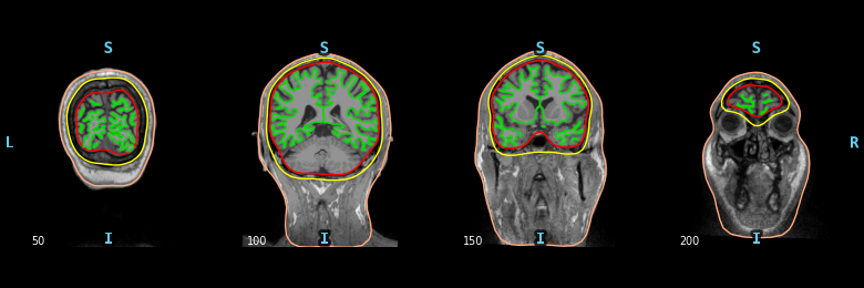
Sorry I got lost with the bounding box discussion but looking at the image it seemed to me that there was some affine registration issue but I might be wrong. I have seen those kinds of images when you do some registration and the corners become black because there are no pixels to copy from. It might be worth taking inspiration from MMVT. Maybe you were also a contributor @alexrockhill ? ;-)
I like how in the sliced view the CT appears in a different color and makes it really easy to spot things. But I don't know if it's a standard way to do this ... |

This is how it was previously in EDIT: for MMVT, Noam was looking mostly at DBS which is usually well-spaced so there aren't bridged contacts and they come out super clean in the thresholded, blue version but with the SEEG CT data I have been working with, the bridged contacts make it so that you really need the background and no thresholding to get the full picture of the contacts. From the experience of actually having done this process for an experiment, I can tell you that the method currently on this branch works better even if it isn't as aesthetically pleasing. Looking more closely, the black rectangle immediately surrounding the skull and the gray rectangle surrounding that are actually part of the underlying image. I really would prefer not to mess with this and the background because you wouldn't want to obscure something that might help you understand what's going on in the CT and it's bounding. The outermost black background is what happens when you zoom out of a matplotlib image so that one could be fixed but again I would strongly prefer to leave it as is. |
|
Looks like the failure is unrelated. Maybe we can get this moving and make more improvements later |
|
Agreed, okay for merge and incremental PRs after this @jasmainak ? |
|
The plan is to do a JOSS paper after this merges so there will be a review there as well |
|
I'm redoing Liberty's ECoG grids with it (I don't have any ECoG that I'm doing for my own research) and besides it not being automated, it works really well |
|
yep +1 for MRG and incremental PRs. Thanks @alexrockhill for the massive effort ! |
|
@larsoner did you mean to remove the directional labels (eg superior, inferior)? I didn't see them when I just used it. |
No, I don't think I meant to do it -- sorry if I did so in some commit. Good for a next PR :) |
|
Thanks @alexrockhill !!! |
Add a GUI that allows users to find their intracranial electrode montage from a CT, an MRI and the Freesurfer recon-all from it, and an
infoobject that supplies the names to be found and is return with a modified montage.Closes #9559
Very rough version, no review yet.