Welcome to the UART Implementation on FPGA project! This project aims to demonstrate the integration of UART (Universal Asynchronous Receiver/Transmitter) communication protocol onto an FPGA (Field-Programmable Gate Array) platform. UART serves as a fundamental method for serial communication between electronic devices, enabling data transmission without requiring synchronized clocks. By implementing UART on an FPGA, this project showcases a versatile and customizable solution for enabling serial communication in various embedded systems applications. Through this project, users can gain insights into FPGA development, serial communication protocols, and practical FPGA-based system design.
UART, or Universal Asynchronous Receiver/Transmitter, is a hardware component and communication protocol used for serial communication between devices. It enables the transfer of data in a sequential, bit-by-bit manner over serial connections such as cables or wireless links. Unlike synchronous communication methods that rely on a shared clock signal between sender and receiver, UART operates asynchronously. This means that data is transmitted without a synchronized clock, with each byte framed by start and stop bits for synchronization. UART is widely used in embedded systems, microcontrollers, communication interfaces, and various electronic devices for its simplicity, versatility, and compatibility with diverse hardware configurations.
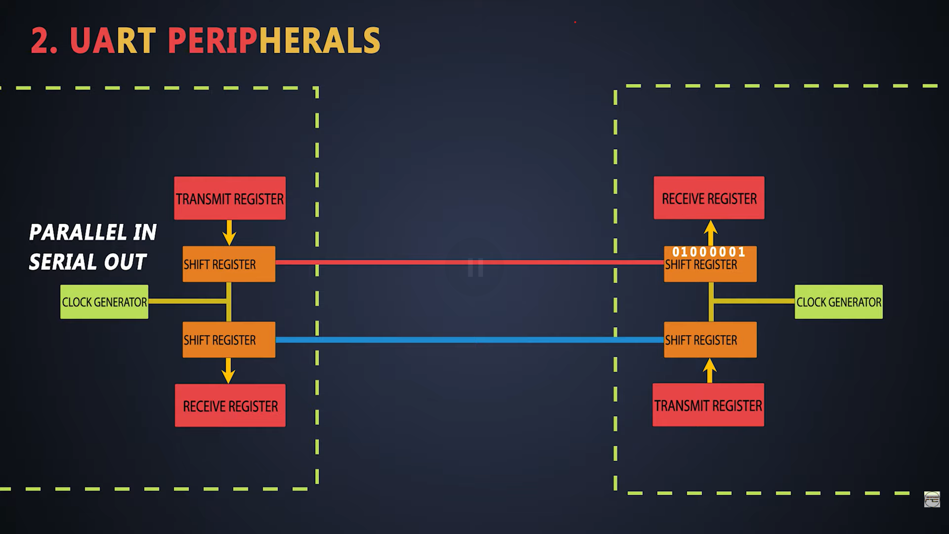
- Parallel-to-Serial Conversion: The transmitter receives data in parallel format from the host device, typically in byte-sized chunks (8 bits). It converts this parallel data into a serial stream of bits for transmission over a communication channel.
- Frame Structure: Each byte of data is framed by start and stop bits. The start bit signals the beginning of a data byte, while the stop bit(s) indicate its end. This framing allows the receiver to synchronize with the data stream.
- Serial-to-Parallel Conversion: The receiver captures the incoming serial data stream from the communication channel. It detects the start bit to synchronize with the data stream and then reads the incoming bits, typically at a predefined baud rate.
- Framing and Error Checking: The receiver identifies the start and stop bits of each byte to extract the data. It performs error checking, such as parity or checksum verification, to ensure data integrity.
- Buffering and Handshaking: Received data is often buffered to accommodate variations in transmission speed or processing time. Handshaking mechanisms, such as flow control signals (e.g., RTS/CTS), may be employed to manage data flow between the transmitter and receiver.
- Baud Rate: The baud rate specifies the speed of data transmission, representing the number of bits transmitted per second. Both the transmitter and receiver must operate at the same baud rate to ensure accurate communication.
- Timing Considerations: UART communication relies on precise timing for bit transmission and reception. Variations in baud rate or clock accuracy can lead to timing errors and data corruption.
- Data Format: UART supports various data formats, including the number of data bits per byte (typically 7 or 8 bits), parity (even, odd, or none), and the number of stop bits (usually 1 or 2).
- Flow Control: Optional flow control mechanisms, such as hardware or software flow control, may be employed to regulate data flow between devices, especially in scenarios where the data transmission rate differs between the sender and receiver.
UART is widely used in embedded systems, microcontrollers, communication interfaces, and peripherals for serial communication. It enables the exchange of data between diverse electronic devices, ranging from simple sensors and actuators to complex networking equipment and industrial machinery.
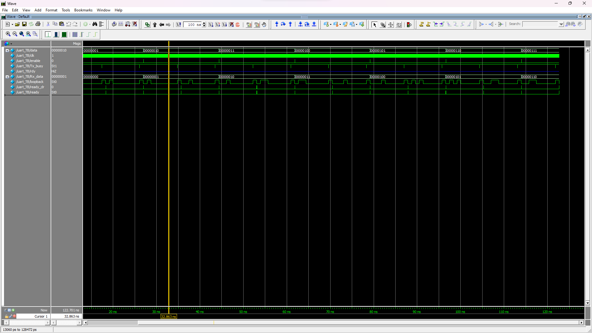
//This is a simple testbench for UART Tx and Rx.
//The Tx and Rx pins have been connected together creating a serial loopback.
//We check if we receive what we have transmitted by sending incremeting data bytes.

//It sends out byte 0xAB over the transmitter
//It then exercises the receive by receiving byte 0x3F
//`include "uart.v"

module uart_TB();

reg [7:0] data = 0;
reg clk = 0;
reg enable = 0;

wire Tx_busy;
wire rdy;
wire [7:0] Rx_data;

wire loopback;
reg ready_clr = 0;

uart test_uart(.data_in(data),
					.wr_en(enable),
					.clk_50m(clk),
					.Tx(loopback),
					.Tx_busy(Tx_busy),
					.Rx(loopback),
					.ready(ready),
					.ready_clr(ready_clr),
					.data_out(Rx_data)
					);
initial begin
	$dumpfile("uart.vcd");
	$dumpvars(0, uart_TB);
	enable <= 1'b1;
	#2 enable <= 1'b0;
end
always begin
	#1 clk = ~clk;
end
always @(posedge ready) begin
	#2 ready_clr <= 1;
	#2 ready_clr <= 0;
	if (Rx_data != data) begin
		$display("FAIL: rx data %x does not match tx %x", Rx_data, data);
		$finish;
	end
	else begin
		if (Rx_data == 8'h2) begin //Check if received data is 11111111
			$display("SUCCESS: all bytes verified");
			$finish;
		end
		data <= data + 1'b1;
		enable <= 1'b1;
		#2 enable <= 1'b0;
	end
end
endmodule
- The testbench starts by instantiating the UART module (uart) and connecting its inputs and outputs to signals within the testbench.
- The data register holds the data to be transmitted, initially set to 0.
- The clk signal generates a clock for the UART module, toggling every time unit.
- The enable signal controls the transmission enable/disable.
- The Tx_busy signal indicates whether the transmitter is busy.
- The rdy signal indicates when the UART module is ready to receive data.
- The Rx_data signal holds the data received from the UART module.
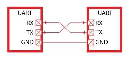
- The loopback signal connects the UART Tx and Rx pins, creating a loopback for testing.
- The ready_clr signal clears the ready signal from the UART module.
- The initial block sets up the testbench by dumping waveform data and enabling transmission initially.
- The clock generation block toggles the clock every time unit.
- The test logic is triggered by the UART ready signal (rdy). When ready, it checks if the received data matches the transmitted data. If it matches, it increments the data for the next transmission. If all bytes have been verified, it displays a success message and finishes the simulation. If there is a data mismatch, it displays a failure message and finishes the simulation.