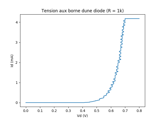
This code permits to plot the diode current as a function of the diode voltage with an arduino uno and an MCP4725 DAC.
You need an arduino uno and an MCP4725 Breakout Board which is a 12-bit I2C DAC. You also need to download the Adafruit MCP4725 12-bit I2C DAC Driver library. On the hardware, you need to plug the MCP4725 DAC to the arduino using an I2C connexion (2 wires). You can search the web for more info about I2C connexions.
For the software, you will need to find the address of the DAC using an I2C scanner and replace the value dac.begin(0x60); with the right address.
The drop voltage or the current in the diode is printed on the serial monitor of the arduino IDE. You need to run the programm twice, one to print the voltage, one for the current. Then the result can be pasted in the python script (for instance) in order to plot the current as a function of the voltage.
You need to place the DAC output on the anode of the diode +. The cathode of the diode - is linked to the ground via a resistor (1K Ohms). The cathode of the diode is also linked to the analog input A0.
If the DAC voltage is too low, the diode is blocked and A0 is at the ground. If the DAC voltage is high enough, the diode becomes conductive. Then the voltage difference is the voltage drop of the component.
VdacOut -- diode -- (resistor -- ground, V A0)
The DAC has values between 0 and 4095, the analog input has values between 0 and 1023. The 0 corresponds to 0 Volt and the max values correspond to 5V.
The voltage across the diode is the difference between the DAC and the A0.
Diode Voltage = VdacOut/4096.*5. - A0val/1024.*5. And Diode current = VA0/R
The voltage drop is limited to 5V. An op amp with a external power supply can handle this limitation, on the DAC output.
ELB - 08/2017

