-
Notifications
You must be signed in to change notification settings - Fork 22
Diagnostics and Troubleshooting
If you wish to run on a PP3 battery: Insert the battery and ensure nothing is connected to the DC input socket.
If you wish to run on a DC suppy: Ensure the supply is a centre-positive 2.1mm barrel with a voltage of between 7 and 24V
Switch on power using the slide switch on the left edge of the lower board. Slide the switch towards the back to switch on.
- Power indicator LED3 should light immediately
- Within a couple of seconds all blue LEDs should illuminate and the CLK indicator LED should start blinking
- Diagnostic indicators LED1 and LED2 on the lower board should blink occasionally
- Press each of the data buttons below the blue LEDs in turn (don't press any other buttons yet). You should be able to toggle each blue LED on and off by pressing the button below it.
- Press and release the HOLD switch. The HOLD LED should toggle on and off.
- Switch HOLD on and press the INST switch. The display on the blue LEDs should change so some LEDs are off some are dimmer or brighter than usual. Within a couple of seconds of pressing INST, press the data button below rightmost LED. The TX button should start blinking.
- Press each menu button PLEN, MODE, SHFT, SPAN, RATE, VELO, GATE, INST, SYNC, CHAN, TRAN in turn. Each time you press a button the display on the blue LEDs should change.
- Press PLEN then PATN - pressing PATN should toggle back to the default display
If all the above tests work, things are looking pretty good! Now we just need to check out the MIDI side of things...
- Connect a MIDI keyboard to the DIN socket below the RX (receive) LED.
- Ensure HOLD is off and press some keys on the MIDI keyboard. Assuming the keyboard is configured to send MIDI notes, and it is connected correctly, the RX light should blink as notes are pressed and release. While notes are held, the TX light should blink and the pattern display should show a moving pointer (brighter blue LED)
- Connect a synth or sound module to the DIN socket below the TX (transmit) LED. Assuming default settings, ARPIE transmits on channel 1, so make sure you are set up to receive on this channel.
- Hold a chord on the MIDI keyboard and ARPIE should arpeggiate this to the synth
All good? Excellent. The one last test is of the MIDI synch input (the DIN socket below the CLK LED)
- Connect a device which can send MIDI synch to the CLK socket on ARPIE and ensure the device is set up to send MIDI clock messages.
- Hold down the SYNCH button for 5 seconds. Ensure the fifth blue LED is showing brightly on. If not, press the button below it to toggle it (default settings will have this setting on). Wait a few seconds for ARPIE to revert back to the main display
- Press SYNCH again and now press the button below the leftmost LED. The LED should light brightly and the CLK LED should stop blinking
- Now start up your MIDI clock source device. ARPIE's CLK LED should blink while the external clock is running and stop when it is not running
If all the above works - congratulate yourself - you just built your own MIDI arpeggiator!
- If you are running from a battery, check that a DC adaptor is not plugged in. The DC supply socket disconnects the battery when a plug is inserted, even if the DC supply is off.
- If you are running from DC supply ensure that the polarity is centre positive and the voltage is at least 7 volts.
- Check that diode D3 is soldered correctly
- Ensure the switch is power switch is soldered properly and is fully slid to the ON position
- check whether diagnostic LED1 and LED2 are flashing. If not, check the orientation of voltage regulator IC5 and electrolytic caps C7 and C8.
- Use a voltmeter to check between the ground (centre) and output (closest to C2) pins of IC5 which should read 5V. Check the voltage between ground and IC5 input (closest to C1). This must be at least 7 volts for the regulator to function correctly.
- If at least 7V is present on regulator IC5 input, but no voltage (or much less than 5V) on the output, suspect the regulator. Check orientation, solder joints etc. Replace regulator if needed.
- Remove IC1,IC2,IC3,IC4 from the sockets and check the voltage present on the socket pins as described in the build instructions. If any voltage is missing, re-check solder joints and PCB tracks. Check for solder bridges (solder blobs shorting between pins or tracks)
- Microcontrollers IC1 and IC2 are programmed to flash diagnostic LED1 and LED2 periodically to show they are alive. If the correct supply voltages are present, but one or both diagnostic LEDs do not light, check the LED orientation (and if possible check the LED with diode test function of a multimeter) to ensure the LED is healthy before suspecting the microcontroller. Please contact me if a microcontroller IC appears to be dead and we can try further diagnostics before deciding if a replacement is needed. All MCUs are tested before packing the kits, but they can be damaged by reverse/over voltage supply or by static electricity discharges.
- Check the connector joining the top and bottom boards is inserted correctly into its socket (It is possible to accidently insert just one row of pins, with the other row overhanging the socket. Check you have not done this)
- Check solder joints on the plug and socket
- Check TR1 is oriented correctly
- Re-check solder joints
- Replace the transistor
- Check the solder joints on the LED
- Check the orientation of the malfunctining LED (The circular outline of LED bulb actually has a flat edge to mark the negative cathode). The cathode for each blue LED should be at the top (towards the back edge of the board)
- If possible test the LED by connecting a multimeter on diode test mode directly to it to see if it lights
- Replace the LED with an included spare
- Check whether you also have issues with one more more of the menu switches. This could indicate an issue with a shift-register output (with one of the small IC's on the back of the control surface PCB). Please contact me for further diagnostics in this case.
- Some flickering is normal, especially when an LED is showing a dim level. This is because the LEDs do actually flicker rapidly due to the multiplexed way they are driven. This should not usually be noticeable unless you are looking for it - or are especially sensitive to it. If this is a real problem for you please let me know - we can probably improve this by adjusting firmware settings.
- If you are seeing erratic behaviour in general, not just with the LEDs, then check the battery is not flat, or power supply level is too low. Check solder joints and ensure the connector joining the top and bottom boards is firmly located. Ensure the IC's are seated properly in their sockets.
This can be the surprising effect of a single LED being soldered in the wrong way around. Carefully check all the LEDs are oriented correctly. This might also result if an LED is failing short circuit (but in this case the faulty LED would not light up, so should be easy to locate and replace)
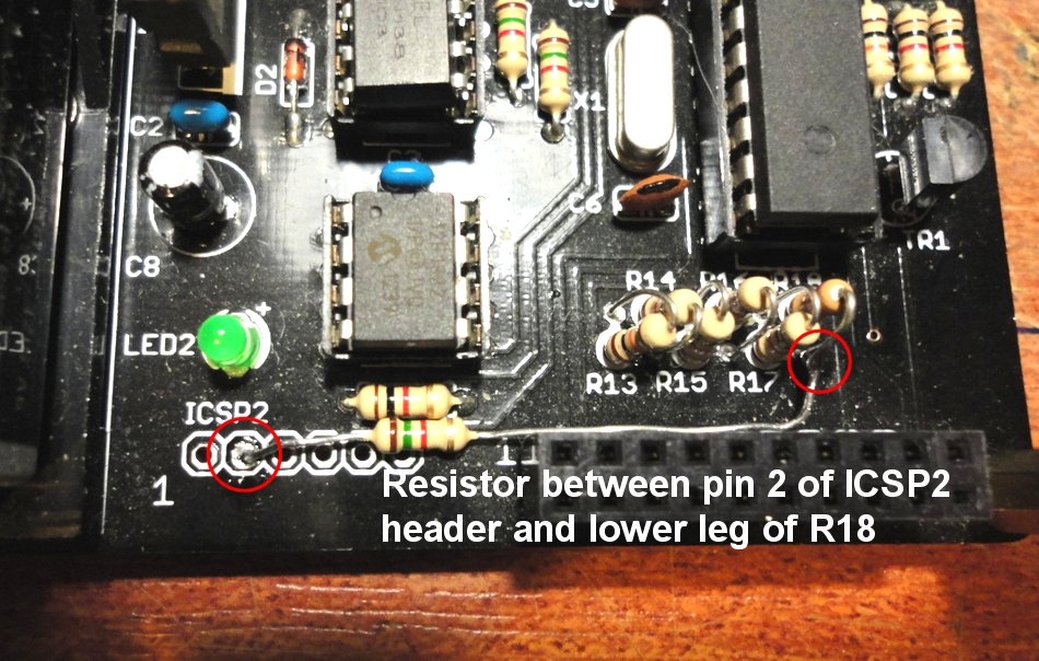
(This might get worse if you lick a fingertip and press it to the exposed tips of the pin header to the lower right of the board). This issue showed up with a particular batch of blue LEDs and it took me a while to get to the bottom of it... the LEDs were sometimes illuminating when their low side was "floating", perhaps due to current leakage through the transistor or other LEDs. The solution is to add an additional pull up resistor between the low side of the LEDs (The STR/strobe pin on the header) and +5V (VCC). https://raw.github.com/hotchk155/arpie/master/docs/images/FlickerFix.JPG shows how I soldered this. A resistor value of 1.5k seemed to resolve the issue. I found the issue before I used this batch of LEDs in kits and I am not aware of anyone noticing the issue with kits containing LEDs from other batches. However if you notice this with your ARPIE, please let me know. The resistor will be added as standard to the PCB design for future kit runs (from Rev4)
If the top (control) board is not working correctly, or at all, here are some diagnostics to try and isolate the problem:
- If you press the HOLD button does the HOLD light come on? The HOLD feature and the other 3 red LEDs are wired independently of the shift register IC's on the back of the control surface PCB. If none of the red LEDs are coming on but the bottom board is healthy then this suggests one of the following (a) The long pin connector is not fitted, soldered, or oriented correctly or pins need cleaning (b) The LEDs are oriented incorrectly (c) There is a break in the ground connection. To test for case (c) use an ohm meter to measure the resistance between the GND pins on the header and the (-) terminal of the battery (make sure there is not a plug in the DC socket since that disconnects the GND side of the battery).
- There should be a low resistance (no more than a couple of ohms) between the GND pins and the battery (-) terminal when the boards are connected together. If there is a very high resistance or open circuit, check for damage between the GND pins and the PCB "ground plane" on both PCBs.
- If there is continuity between the pin header and the battery, check between the GND pins and the switch legs to the lower right side of the HOLD button - these should be connected. An open circuit here would isolate the issue to the ground plane on the upper board. Check for PCB damage below the header.
- Here are some tips to check the red LEDs: (a) The HOLD LED should come on when you press the HOLD button (b) The CLK LED should blink when you are using internal synch (c) The RX and TX LEDs should blink when you connect a MIDI keyboard to MIDI IN and play notes
- The blue LEDs and the buttons (other than HOLD) are driven by the two small shift register components on the back of the board. If the blue LEDs are not working, it is difficult to know if the buttons are working or not, but this is important to help us isolate the issue. Here is a test we can do to see if the keyboard is working even when the blue LEDs are not: Assuming the SYNCH LED is blinking, press the SYNCH button once then press the small switch below the first blue LED. This should stop the SYNC LED blinking (as we switch off the internal synch). Repeating the same should start the SYNCH LED blinking again. You can also try changing tempo when the LED is blinking by pressing SYNC then one of the middle LEDs. If these tests work then it suggests (a) The shift registers are OK (b) The problem is with the low side of the blue LEDs, which pass through the STR pin on the header to transistor TR1 on the main board. Check PCB tracks and solder joints, including transistor TR1, Resistor R18, Resistor R11, IC socket connection for IC1.
- Another test you can carefully do is to briefly short the STR pin to the GND pin below it, using the blade of a screwdriver. If all the blue LEDs come on brightly then this suggests the shift registers are working and the issue is either the connector or the base board (do not light the LEDs too long this way since there is no series resistor to limit the current, so the LEDs could possibly be damaged)
- If the above tests fail then the shift registers, or the connections to them, could be damaged. These components are pre-soldered and tested before being placed into kits, so this should be less likely than issues with other components or joints. However it is worth checking that no solder debris has got attached to the legs of the shift register ICs causing shorts, and that no damage (scratches etc) has occurred to the tracks.
- The following shows the layout of the top side of the header pins (lower right corner of control surface) as they are exposed when the boards are connected together
CLK, DAT, KS1, LD1, LD2, LD3, LD4, STR, SW1, KS2
VCC, VCC, GND, GND, GND, GND, GND, GND, UN1, UN2
- Ensure that the ARPIE input channel is set correctly
- Ensure that controller device is set up to send notes/synch and (for notes) that the send channel on the controller matches the input channel on the ARPIE
- The RX LED should blink as notes are received. If RX does not blink, but otherwise things seem to be working, check the orientation of the LED and if possible use a diode test mode on a multimeter to check the LED. Replace the LED.
- Ensure MIDI lockout is not engaged (HOLD flashing). This mode causes ARPIE to ignore all input. Press HOLD to disengage, or power down/up.
- For external synch issues, check that synch source is set to external and that the global options for synch settings are configured to use the required input source
- Check the solder connections to the MIDI input sockets and ensure that all legs of the sockets are connected properly
- Check opto-isolators IC3 and IC4 are oriented and inserted correctly
- Check diodes D1 and D2 are oriented correctly
- Check that microcontroller IC2 is inserted correctly. Diagnostic LED2 should flash 3 or 4 times on power up and should then blink periodically. IC2 is responsible for receiving the MIDI from the CLK socket.
- Does the TX LED flash? If TX is flashing, ARPIE is trying to send MIDI data. Check the MIDI channel selected for ARPIE output matches the input channel of your synth. Check solder joints to the output MIDI socket and resistors R1-R4. Ensure IC1 is inserted correctly.
- If the TX LED does not flash when notes are being sent, check the orientation of the LED and if possible use a diode test mode on a multimeter to check the LED. Replace the LED.
- Make sure you have selected board type "Arduino Duemilanova w/ATMega 328"
- Make sure you have the correct COM port selected
- Make sure you have the correct drivers for your USB-TTL device
- Try closing and re-opening the Arduino environment (especially if you have just connected USB-TTL device while Arduino environment is running)
- Try rebooting your computer (especially if you have just installed drivers for a new USB-TTL device)
- Check wiring between the USB-TTL device and the header on the board
- Depending on the type of USB-TTL device you may need to reset the board when the Arduino environment shows "Uploading"
- Locate and open boards.txt (within your Arduino installation in a hardware/arduino folder)
##############################################################
atmega328.name=Arduino Duemilanove w/ ATmega328
atmega328.upload.protocol=stk500
atmega328.upload.maximum_size=30720
atmega328.upload.speed=57600
atmega328.bootloader.low_fuses=0xFF
atmega328.bootloader.high_fuses=0xDA
atmega328.bootloader.extended_fuses=0x05
atmega328.bootloader.path=atmega
atmega328.bootloader.file=ATmegaBOOT_168_atmega328.hex
atmega328.bootloader.unlock_bits=0x3F
atmega328.bootloader.lock_bits=0x0F
atmega328.build.mcu=atmega328p
atmega328.build.f_cpu=16000000L
atmega328.build.core=arduino
atmega328.build.variant=standard
In this block, if your setting of atmega328.upload.protocol is set to arduino try changing to stk500. Save the file and restarted the Arduino environment.