Home
 TobyJnr is an evolution of TJBot. It is driven entirely by Node-RED running on the Raspberry Pi inside TobyJnr and also has an optional SenseHAT. The SenseHAT allows TobyJnr to be controlled via the joystick on the SenseHAT. It also provides environment and motion sensors and an 8x8 LED panel for feedback to the user.
TJ Bot => Bot reversed and now shares T - Tob J => add Node-RED (NR) - Tob Jnr => add a y -> TobyJnr
This wiki will walk you through the steps needed to build and configure the hardware and software needed to implement your own TobyJnr.
The list of hardware needed to build TobyJnr is:
- Raspberry Pi 3 Model B (+ SD Card, + microUSB cable + power supply)
- NeoPixel Diffused 8mm RGB LED (or other WS2812 based RGB LED with integrated controller - These usually have 4 connectors +, -, DataIn, DataOut).
- Tower Pro SG90/SG92 Mini Servo (to move the arm)
- Raspberry Pi SenseHAT
- Raspberry Pi Camera
- USB Mini Microphone dongle
- USB Bluetooth 4 dongle (Yes, the built in bluetooth is not reliable so will be disabled if using a bluetooth speaker)
- Bluetooth speaker (I have tested with a betron BPS-60 and an EasyAcc Mini portable Bluetooth 4.0 speaker, but others should also work). You can a USB speaker or sound card instead of Bluetooth, so long as it doesn't require the audio signal from the 3.5mm socket - there is a wiki page looking at Sound options for the Raspberry Pi and TobyJnr
- Connecting wires (Male <-> Female and Female <-> Female)
- A body for your bot which can be lazer cut or 3D printed (see here for details)
Follow the instructions in the above link to get the parts needed to build and assemble the body. If you want to mount a SenseHAT to the front of your bot you will also need a hole at the top of the front face of the head 52mm X 6mm to allow the connector to pass through the head and a couple of M3 bolts with washers and nuts to hold it in place.
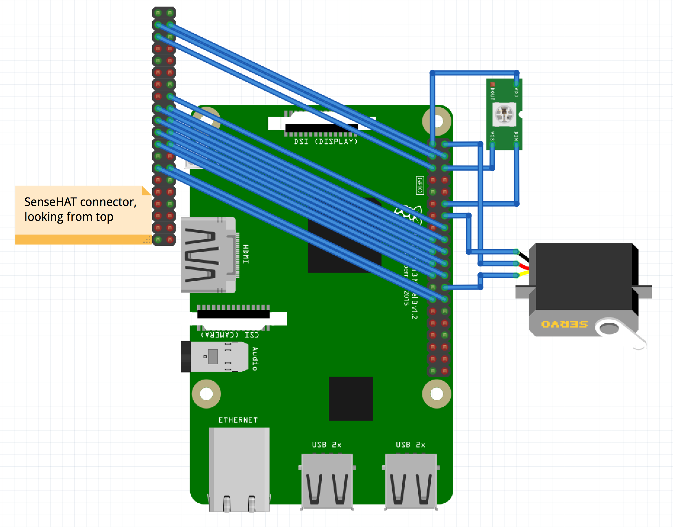 Wire the TobyJnr according to the above diagram (LED and Servo match instructions for TJBot). The connections for the 3 components are also listed below, showing which Raspberry Pi pin number on the 40 pin connector for each connection:
- LED : +'ve : pin 1; -'ve : pin 6; DataIn : pin 12
- Servo : +'ve : pin 2; -'ve : pin 14; Data : pin 26
- SenseHAT : connect pins with same pin on Pi : 3, 4, 5, 16, 17, 18, 19, 20, 21, 22, 23, 24, 27, 28 There is additional information about wiring the components on the pages dealing with GPIO and the SenseHAT