Project Summary: The purpose of this project was to build a line-following robot using our learned knowledge of circuits and coding. To complete this we use the Arduino kit, a simple car chassis with two wheels connected to two DC motors, also implementing two photocells, two NPN transistors, and a buzzer. The line following robot works well despite the type of line it must follow. We added a buzzer so that it would sound off whenever the robot makes a turn but not when it was going straight. There were some issues that we encountered while building the circuit in that the photocells stopped working and either had to be replaced or put back into place because they would move around from their original placement, and would cause the rest of the circuit to operate incorrectly. We also encountered issues with getting a readings for the white surfaces and black surfaces, thus causing inconsistent light thresholds. To address this, we simply used a constant for the light threshold, and programmed the button to start the car, so it would not begin running the moment it was connected to a power source. There was an issue with the car chassis, in which it had to be replaced because the soldering of the ground wire to the motor broke and could not be reattached by hand. Once these issues were corrected, the final variable that caused inconsistencies was the placement of the photoresistors. To address this we tested the car on multiple tracks with varying line widths and lighting conditions until the robot was able to follow every track it encountered.
Circuit Schematic:

Circuit Description: The buzzer, NPN transistors and button are all connected to pins 4, 8, 9 and 2 respectively. The wire that connects ground on both sides was used to make connecting the resistors easier and not have to use a wire to connect them. The NPN transistors were used to amplify the signal from the pin and to the LED, which was an indicator other than the motor that the photoresistors were working. The cathode of the LED was connected to the collector of the NPN transistor and the anode to 5 volts. The emitter on the transistor is connected to ground because it was not needed to make the circuit work. The base on the transistor was connected to a 330 ohm resistor and to the pin so that it would be able to detect the changes from the photoresistors. This was done so the motor would be able to rotate based on what the photoresistors detected instead of rotating on their own. The left motor had the positive (red wire) connected to 5 volts and the negative (black wire) to the collector of the transistor so that the wheel would turn clockwise. The right side motor was connected in the opposite manner in that the red wire was connected to the collector and the black wire to the 5 volts because if it was connected the same way as the left motor it would rotate the wheel counter clockwise instead of clockwise. The buzzer is connected to ground without resistor so as to ensure the tone could be heard when the robot made either a left or right turn, but not so that it produces a sound when the robot is going straight, otherwise notes that both photocells are registering as “HIGH”. The photoresistors were connected to pins A0 and A1 because they are analog inputs because they are detecting the change in light based on the track in front of them. Additional resistors are used when connecting the photoresistors to ground to maintain a constant resistance since the photoresistor itself is a variable resistor and changes due to the light intensity it detects. The button has one leg connected to a 10k ohm resistor that goes to 5 volts and the other leg to ground so that it would be able to start the circuit when the button is pressed.
Flow Chart:
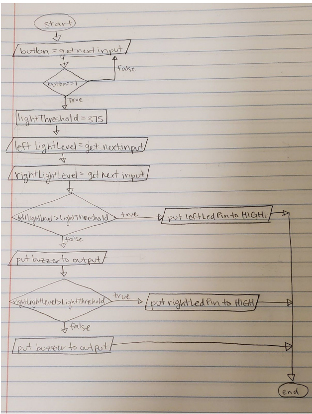
Flow Chart Description: The circuit begins working once the button is pressed, meaning the counter becomes 1, otherwise it will wait until the button is pressed to begin. Once the button is pressed, sensors begin detecting the light on the right and left of the track. The light threshold is set at 375 making it a variable that can be used in later decisions. The first one being the leftLightLevel > lightThreshold in that the buzzer will sound off if it is false, meaning the car will be turning right, but if it is true the leftLedPin will go to high which is connected to the motor making it so that the left motor will rotate the wheel. Since it is followed by another if else statement for the right motor it is set to the decision rightLightLevel > lightThreshold for the same reason as the left motor. The function is a Loop function, meaning it will continue iterating so long as power is supplied to the Arduino.
Testing:

The robot was tested a multitude of times on homemade tracks; varying from straight lines to vigorously twisting and turning. Using a line that had two (2) turns as our basis for the robot operating proficiently, we adjusted the light threshold constant and positioning of the photocells accordingly until the robot could follow given path's consistently. Margins of error occured when the car was placed more than (about) eight (8) inches from the desired path it should follow, and when the given path extended over numerous papers because the photocells may not detect the black tape or path. Although programming the photocells and car to take readings of the white space versus black lines was part of the assignment, it was not possible with the given equipment and lab environment.