IBIS Getting Started
Work in progress
The intention of this manual is to describe the IBIS interface and give the user examples of simple applications.
To get a general idea of some IBIS functionality see the short movie Intraoperative Ultrasound with IBIS demo
The application operates on graphic objects. These are the object types used:
- Image Object, obtained by loading an image file (.mnc, .nii, .dcm, etc.). It is represented by 3 planes - Sagittal (X Plane) , Coronal (Y Plane) and Transverse (Z Plane) as shown on Figure 1.
- Polydata Object, used to represent 3D structures, usually a surface or a mesh.
- Camera Object, represents a camera.
- US Acquisition Object - series of 2 dimensional Image Objects showing images acquired by doing a sweep with the US probe.
- Points Object consisting of several points, each represented by a sphere in 3D view and a cross with a circle in 2D views.
Additionally there are helper objects:
- Generated Surface - a surface made from Image Object data.
- Landmark Registration Object - used to perform a rigid registration, consists of 2 sets of points. (See Landmark Registration.)
There are also three system objects that can never be removed:
- World Object - a direct or indirect parent of all the other objects.
- Image Planes Object - an object used to represent Image Objects.
- PRISM Volume Renderer - renders a volume of the selected object.
Together all the objects loaded or created in IBIS form a "scene". If there are some Image Objects in the scene, one of them is called "Reference Object" (just Reference later in the document) and it is chosen by the user. The Reference name is displayed in red on the list of objects in the left side dock.
When you launch IBIS, the Main Window will pop up. Figure 1 shows an example of a Main Window with an object already in scene. Main Window consists of a menu bar, a toolbox, 4 views, and the left side dock. Figure 1 shows also an object added to the scene to help understand the GUI. This image is a "Reference" object. The text in red is there to describe the views and their orientation, it will not show in the application.
 Figure 1. Main Window
- Zoom In - all 4 views.
- Zoom Out -all 4 views.
- Fit To Window - all 4 views.
- Expand Selected View - selected view has a red frame around, when expanded, the other views will be hidden.
- Reset Planes - all the planes will be moved to the initial position.
- View Front - place the Reference facing the the camera.
- View Back - place the Reference back-side towards the camera.
- View Right - place the Reference right-side towards the camera.
- View Left - place the Reference left-side towards the camera.
- View Bottom - place the camera under the Reference.
- View Top - place the camera on top of the Reference.
- Cursor Position - shows cursor coordinates in image space. The orange cross over the object in all views represents the cursor.

Figure 2. File Menu
The File Menu lists the operations that can be done on files - opening, saving, etc.

Figure 3. Open File Dialog
Selecting File Menu-> Open File, will show the dialog above. Clicking on the "..." button will allow you to browse for the file. A drop down list shows all the possible objects that accept children. The default parent is the World Object. If you open a label image, you will need to check the appropriate box.

Figure 4. New Object
File Menu -> New Object, will present you with a choice of object to create. Point Set will create an object that allows you to select points using mouse. Generate Surface will show only if your currently selected object is an image and will let you create a corresponding surface that will show in 3D view. A Landmark Registration object will create an object consisting of 2 point sets used to perform a rigid registration of the object in the world system. See Landmark Registration.
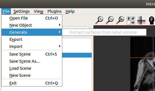
Figure 5. Generate
File Menu -> Generate, will let you generate a surface of the currently selected label volume. It will be grayed if the selected object is not a label.
This is only available if the currently selected object can be exported to a file. Surfaces are exported as VTK (.vtk) files. Images are exported as MINC2 (.mnc) files, acquisitions are exported as series of MINC2 (.mnc) files. Landmark Registration is exported as an MNI tag (.tag) file.

Figure 6. Import
Two types of objects can be imported - previously saved US Acquisition or Camera object.
All the objects represented in IBIS application form a scene. This scene can be saved for later viewing. All objects in the scene will be saved together with their properties (position, color, etc.) in a user selected directory. The scene properties are describe in the file scene.xml. Do not edit this file manually. Selecting Save Scene repeatedly will overwrite the previously saved scene.
Use this option when you want to save a scene without overwriting the last one saved. It will let you select a different directory for saving, leaving the previously saved scene intact.
Use this option to load a previously saved scene. Select scene.xml file when prompted. If you have any object already on the scene, you will be asked to confirm removal of that object.
Choosing this option will let you to remove all the objects currently in the scene.
Quits the application instantly.
This menu is used to control hardware configuration and to set paths to frequently used applications or directories. IBIS is communicating with external devices using Plus Toolkit. The first thing to do is setting the path to Plus Server using option Preferences.

Figure 7. Settings Menu
Selection of the configuration file that describes tracking tools used in the scene.

Figure 8. IGSIO Configuration File
The pull down list contains all the configurations file from the directory ~/.ibis/IbisConfig/PlusToolkit/IbisPlusConfigFiles. Select the one that corresponds to your tracking tools and click on Apply. You may check the box "Automatically start last config" if you want to use it in the next IBIS session.
Selecting Preferences will present a dialog allowing the user to set the PlusServer executable, the path to the MINC tools directory, or any other path or executable file that has to be configured for IBIS to work.

Figure 10. Preferences
Clicking on "..." button will allow you to select a path or an executable in the file browser.
Lets look at Figure 1 again. It contains one image in the scene - the Reference. All the actions in the View menu will place that object in a specific way on the scene. If there are other scene objects related to Reference (e.g., children objects) they will move together with Reference.

Figure 11. View Menu
- X Plane - show Sagittal plane in 3D view.
- Y Plane - show Coronal Plane in 3D view.
- Z Plane - show Transverse plane in 3D view.
- View All Planes - show all 3 planes in 3D view.
- Hide All Planes - remove all planes from 3D view.
- View Front - place the Reference facing the the camera.
- View Back - place the Reference back-side towards the camera.
- View Right - place the Reference right-side towards the camera.
- View Left - place the Reference left-side towards the camera.
- View Bottom - place the camera under the Reference.
- View Top - place the camera on top of the Reference.
- Reset Planes - put all the planes in the initial position.
- Full screen - Expand the selected view (the one with the red frame).
This menu lists all the plugins that have been enabled during the process of building IBIS.

Figure 12. Plugins.
To use one of the plugins select it on the list.

Figure 13. Help
The Help menu contains 2 items: "About" and "About Plugins".
Shows application name and version.

Figure 14. About
Shows all the IBIS plugins.

Figure 15. About Plugins.
The left side dock describes elements of the scene.It consists of 3 parts:
- Tracking tools and status.
- List of objects in the scene.
- Settings and parameters of the object selected on the list.
Placed on the top of the left dock, it shows the ist of tracked tools and their status.

Figure 16.
Clicking the "Navigation" checkbox will allow you to see the current pointer position in all views. Clicking the button "S" will show a snap shot of the transformation matrix of the tool.
The Objects Tree shows the hierarchy of objects in the scene. All the objects are direct or indirect children of the World Object. You may manipulate user added objects changing their parents or removing them from the scene.

Figure 17.
- Delete the selected object.
- Add a transform as a child of the selected object.
- Add a transform to all children of the selected object.
- Add a transform as a parent of the selected object.
This part of the left dock shows the settings and properties of the selected object. We will show the Image Planes settings as an example.

Figure 18.
Here you may decide which planes to show in the 3D view, set the interpolation type and slice thickness as well as configure the Image Mixer.
Start IBIS, you will get a Main Window as on Figure 19.
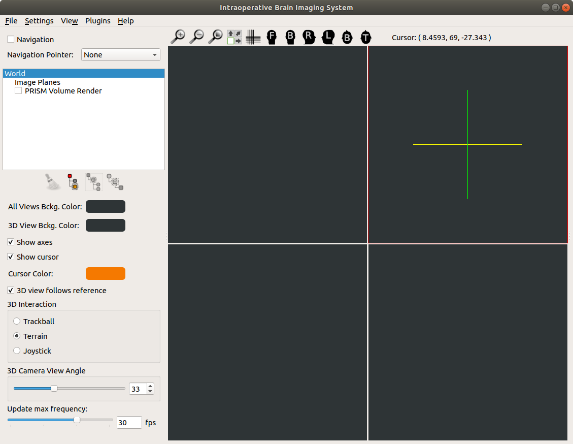
Figure 19.
As there are no objects on the scene yet, you may play with World settings only and see how they change the views. We suggest setting the background color of all windows to different than black, Image Planes will show better later.

Figure 20.

Figure 21.