- Plug in the device to your computer
- Run
ls /dev/tty*in your terminal to find out the USB-path of the ESP8266- if you have difficulties finding the correct path you can run the command twice; once with the ESP connected, once without
- Follow the guide to get the basic firmware installation done.
NOTE: The installation assumes that the port name of device is /dev/ttyUSB0, use the port name you found with ls /dev/tty* instead. Also make sure to change the firmware directory to the one you downloaded (we tested with esp8266-20210418-v1.15.bin).
You will need a way to view the serial terminal so it's best to make sure you have screen installed or something similar.
This guide will help with that part.
For uploading and working with the board I use mpfshell which you can install as follows:
pip install mpfshell
If you are using linux, you will have to grant permission to your user to access the serial.
You can simply add your user to the uucp or dialout group in order to do so.
sudo usermod -aG uucp my_username
sudo usermod -aG dialout my_username
Remember to log out and back in for the changes in the user groups to take effect.
Next, let's try to upload the blink sample code. You will see that the code is all contained in a boot.py script. This is because the micropython firmware will automatically try to run the code in a boot.py file once it is uploaded to the board.
Replace the cu.usbserial-310 with the appropriate usb port on your system (remove the /dev/ part of the path you've been using at step 1).
mpfshell --open cu.usbserial-310 -nc put boot.py;
note: If you have not followed the steps for user permissions in the beginning of this guide, here is where you will find out. If you are getting permission denied, reffer back to the first session of the guide for information.
You are done! The LED should have started blinking
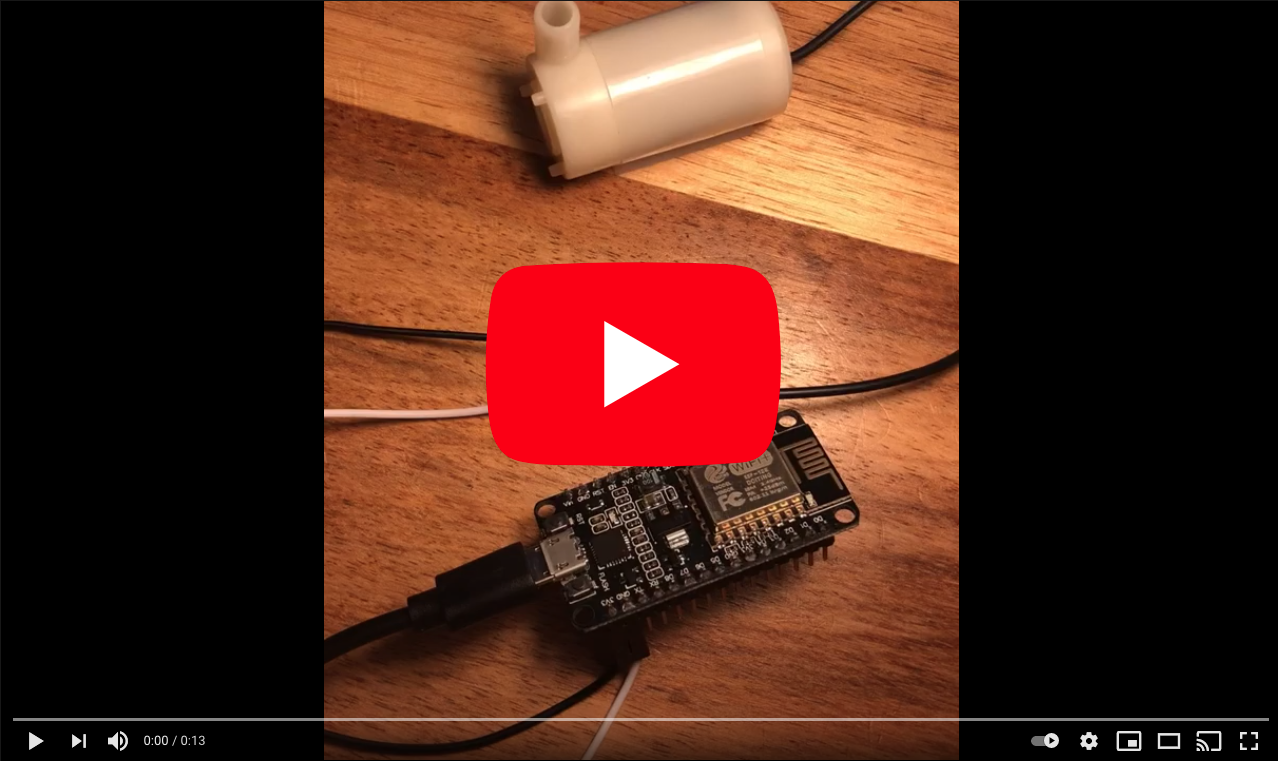
- Strip the red and black wires of the pump.
- Plug the ESP8266 into your laptop or a cellphone charge using the MicroUSB cable.
- From your water pump press the red wire onto the 3V3 pin and black to GND pin or hook them up using the dupont wires.
- You should hear the motor of the pump spinning.
Alternatively
- Use a 3V battery and press the wires directly onto it.
Troubleshooting:
Please help us spread the word about Make events so that we can grow the community and keep helping devs learn new tech 🚀 💦 🌱.
- Use the phrase
#OfferZenSwag with @offerzen. - Share a photo or story on: Twitter, LinkedIn, Instagram or Facebook
See you online soon <3
Here's a fabulous example from @hendrikdelarey

On linux, if you want to check what the arduino is outputing to the serial (the test program outputs ON and OFF, as the LED changes state), you can do so by connecting to the serial port using screen, in this example /dev/cu.usbserial-310. This would look something like:
screen /dev/cu.usbserial-310 115200
It's important to note that you need to connect to the serial at the right baud rate. By default it is 115200 kbps.