Edge Detection failed on atlas annotation file #16
Comments
|
Update: I tested the idea i posted before and the result seems a lot better, but now it doesn't finally close the regions (i.e. some gaps on top and at the sides). Why does this happen? |

|
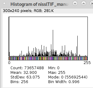
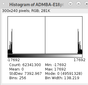
Hi @SaibotMagd, thanks for asking! Glad to hear the later result looks better, but yes the edge gaps look strange and something I haven't see before. Could you let me know what commands you ran and any specific setting? I haven't actually seen the type of image from your first post either and wonder how you got that one too? Maybe something I can improve in the docs. The signed symmetrical color scheme shouldn't affect the edge generation since the color scheme is just for visualization in the GUI. The atlas mirroring during import does makes label values negative to distinguish hemispheres (as seen in your histogram), but you can turn off the negation by adding the Are these atlas images 2D or 3D? I haven't tested edge detection on 2D images yet and it's possible they're related to the gaps. |
There's nothing specific I just use the command in protocol 5 step 5:
Well I tested it using the symmetrical sign and the unsigned image and the result is different, so it seems like there's an effect.
With unsigned symmetrical pictures I tried 2D and 3D, same results either way. In the signed symmetrical version. and the edge detection result: So the result for 3D signed symmetrical images is the same like 2D unsigned. I don't get it. Maybe it have nothing to do with the signed/ unsigned stuff at all. |


|
Update:
Another idea: "I tried a 2D annotation file and a 3D atlas file and it fails. Does the code use the atlasVolume file to create the edge annotation file?" |

|
The screenshots are really helpful, thanks for going through the scenarios and posting them! I can reproduce the gaps now on a 2D image. I extracted a single 2D plane from a 3D image and see at least a couple gaps that aren't present on the corresponding plane in the 3D image. Edges generated on 3D annotation file: Edges generated on 2D annotation file: I also extracted every 50th plane to give a 3D image with large jumps in label position/size/presence between each place and can reproduce the types of images you showed with very thick edges. Edges generate on 3D annotation file reduced to every 50th plane: I didn't see any differences with unsigned images (manually converted after taking the absolute value) so am not sure what the cause might have been there. Edges generated on 2D annotation file, converted to unsigned int: The underlying cause is most likely that the edge algorithm used here doesn't handle 2D images or thin/irregular 3D structures so well. This is something to improve. Only the Ah, and thanks for pointing out my |


This seems like a valid explanation.
I could create a edge detection file from other unsigned 2D annotation plates even without the atlas_profile parameter. So sometimes it works well, but the gaps still persist.
I think I try to go further on multiple 2D slices and stack them afterwards. |
|
Sounds good, let me know how it goes. I'll flag this issue for improving the label/binary image perimeter algorithm, particularly for 2D cases. Thanks again for reporting it! |
|
So after I used a bspline registration on the source plates to create a more smooth dataset it creates nice edges for the annotation as you saw here: #45 But this isn't working in coronal direction. So the issue isn't about the "gap" between the slices, because its the same image-stack. I guessed it could come from the "unusual" size of the imagestack (they are 1416x839x270). But this isn't the case: Why do I even try to do it in both directions? I registered the nissl slices multiple times (depending on manuel visuel inspection) onto several 2D slices from the 3D lightsheet-image to interpolate the 62 slices to 270 slices. As you can see, it went okay-ish. But to increase the match I want to smooth the annotations onto the 3D Lightsheet image after the registration. It is only natural to do in coronal direction since the initial annotations were created in this perspective. And it is also important to compare the edge-DSC between coronal and horizontal direction smoothing (either one time or two time smoothing). Here again the unsmoothed result for horizontal direction: |


|
Thanks for posting this. So the refinement worked well when using horizontal sections, but not coronal planes? And your original annotations are in coronal planes, so ideally the refinement would work coronally for your atlas? Did you get that refinement working in the horizontal sections in #45 by registering each of your (coronal?) source plates with b-spline (and interpolating plates by additionally registering at intermediate positions?) to the 3D lightsheet image, and the watershed interpolated the source plates to create a full 3D set of labels? Are the images here in this post from the same refined atlas output in #45, but now shown in the coronal view, or a new refinement? Sorry if I am not fully understanding everything. I agree that the refinement looks better in #45 than here. |
Yes as I showed in #45 . I did not try coronal refinement yet.
Yes that's what I did. I registered the original 2D nissl plates onto a lightsheet image slice-wise in 2D. For example: The left numbers are the original 2D coronal nissl plates (there're 62), and the list shows the lightsheet slices I registered onto. I downsampled the LS-image to match the coronal resolution from the nissl plates so I get an isotrophic resolution (50um = [214,127,270]). The what you called a "intermediate position" is a non-linear gap filled by a various number of registered slices (62 nissl plates registered to 270 LS-slices, some just once others 9 times) to match the isotrophic resolution.
No it is the identical image stack just resliced in imageJ from coronal view. The segmentation (annotations) were originally defined on coronal slices and the registration is also done in coronal direction. In #45 I showed the result from the "merge_atlas_segs" step (that's why its smooth). The images above are just from the "make_edge_images" step. I will try the merge-seq also in coronal direction. |
|
The edge refinement in coronal direction seems similar as in horizontal, so this isn't a real problem right now: The result of the refinement step shows the main problem, I'm afraid of as I mentioned before #45 : So to make use of the refinements the majority of regions need a reasonable amount of borders. If there's a lack in borders the region tend to become a blob. I think that's no surprise because of the extensive use of erosion. But what is "a reasonable amount of borders" #45 ? |


|
Thanks, I think I have a better understanding now. The intermediate slice b-spline registration is clever. In the coronal refinement output image you showed, are the left slices from your original atlas, and the right slices are the same slices after refinement? If excessive erosion is an issue, you could try dialing down the erosion to preserve the original labels more. In the atlas profile, the For the morphological smoothing step after the refinement, the smoothing could be giving the blob-like shapes. The magellanmapper/magmap/settings/atlas_prof.py Lines 478 to 481 in 65545c8 You could edit the file manually (just need to git stash/commit changes before later pulling in updates to avoid conflicts), or create a new profile (see #49 (comment) for more info). |
Probably, but I think I overdid this. 62 into 270 (50um resolution) is to much for such a kind of an interpolation. I should decrease the resolution (to 100um), so I only have to fill 50% of the slices.
Yes its the same slice. Fiji only messed up the LUT, but the grey values are also correct.
I tried some other parameters but it doesn't change a lot. Maybe it would be better to drop all regions if they cannot hit at least one histological border after dilation. But anyhow if I go down to 100um resolution I have to drop at least 50% of all regions myself because they will be to small to even plot them. I calculated the size of each region so a size threshold could work, but either way these regions have to be collapsed into regions nearby. So more knowledge about histological structure is necessary to do this, I can't provide. |

Yeah that sounds like a good start, and then you could always add more slices later if needed.
I agree that the refinement made the labels rather blob-like when comparing the left to the right in your image. I have seen that before with larger marker erosion sizes and fixed it by using really small values in some cases, like even 1. Using small erosion sizes would at least preserve most of your original structure. Also, if you set all those parameters to 0, does it reproduce the left side? |
|
Because of the ongoing issues with the edge detection for the annotation file I created my own version. Instead of using a canny like edge detector I abused the fact that each region for each annotation label consists of a homogenious surface, so I calculate the gradient to edge detect for every label and then merge the several edge images together: It runs 8 min for a 370 MB annotation file, but I think a "real" programmer could easily optimize it. I also tried a 3D version but the result is really bad and it runs about twice as long. |


|
This edge detection looks excellent! It would definitely be a great addition as another edge detection approach, especially for 2D cases. Would you be interested in opening a PR with the code you have so far, and we can work on it together there? We could add it to the cv_nd module.
I agree that your filter 6 has a good balance of smoothness without losing too much definition or becoming blob-like like at filter 8. Just to clarify, are the edge detection issues you're seeing in the filter 8 image these thick areas, probably from adjacent edges parallel to this plane?
Your gradient approach would be a nice option to address this. |

Sure I always try to work on improvements, but I have no idea how to do this and I don't think I find time to try this out. My Deadline is so soon and there're so many issues left. But I add this to my to-do list.
I don't think I understand what you mean by this. So lets take an easier and more precise example: So for me it seems like this brings some evidence for my suspicion: "the displacement of an particular label on consecutive slices is to large" and this breaks the edge detection because it uses this 3. dimension. I think it would be important to know what "to large" actually mean, so magellans edge detector could calculate the displacement and switch to the gradient-type of edge detection if neccessary. |


Sure, no problem, just want you to know the door's open and that we can work on this together.
Yes, thanks for clarifying, your arrows there are exactly what I was referring to as well.
Yes, I think the different approaches would benefit different applications. Your gradient approach appears to work nicely for your 2D planes and would be a useful option for those cases. |
|
Unfortunately i just found out that my gradient based edge selection destroys labels. I try to find a solution. Update: the problem is that the gradient calc leads to different values when a region have multiple borders, so it can't work. The more common solution is to use the "findContours" function like this: I have to do more testing but the first try nearly halfed the runtime and preserved all labels. |
|
Great solution! Thanks for sharing it, and glad it has the double benefit of running faster in addition to retaining all labels. We could certainly incorporate this as an edge detection option too at least for the 2D case, and it may work for 3D as well. Thanks for finding it! |
|
Update: it still doesn't work good enough. It looses one single label and I can't find out why. |
|
Which label gets lost? If it's a small or unusually shaped label, it may be escaping the contour detection. You could try adjusting parameters for any labels that would be lost to see if they can be preserved. |
I don't know it isnt an unusal shaped label. I just changed the code and now it works fine, but I don't understand the difference from the old to the new code. I'm just playing around because i didn't know what to do to solve the problem and come up with this solution. This is what non-programmers are doing most of the time? This is the new one: " As far as I can understand the code in the old one it saved only the "corner"/ "turning" points for the frame (approx_simple) while "edges[i] = np.zeros_like(edges[i])" did actually nothing, but the code doesn't work without it. In the new version I saved the whole frame structure (approx_none = all pixels on the frame will be saved) of the region and just draw it onto the particular slice (after resetting the slice to 0). So you could be right, the number of "turning" points could be so unusual or impossible to calculate that the "approx_simple" function saved nothing for this particular region. |
|
That's awesome you solved it! Yeah makes sense that Nice coding there! |
|
As I found out most recently, the issue regarding the edge detection is even more severe lets look at the images created for the Gubra LSFM Atlas (Perens J, Salinas CG, Skytte JL, Roostalu U, Dahl AB, Dyrby TB, Wichern F, Barkholt P, Vrang N, Jelsing J, Hecksher-Sørensen J. An Optimized Mouse Brain Atlas for Automated Mapping and Quantification of Neuronal Activity Using iDISCO+ and Light Sheet Fluorescence Microscopy. Neuroinformatics. 2021 Jul;19(3):433-446. doi: 10.1007/s12021-020-09490-8. PMID: 33063286; PMCID: PMC8233272.) Edge Detection for the AtlasVolume: Original AtlasVolume file looks like this: Also the Annotation Edges arent't correct for the same atlas: This is so bad because I did a comparison between my atlas and the gubra and later creates suprisingly high values on the distance metric (more then 3 times as large as all of my other atlases even if they're quite bad). I used my own edge detection for the annotations but don't know if I'm able to do this for the atlasvolume. I turn the Gubra Atlas Volume and try it again. |


That does look strange. I wonder if it's because the images look relatively blurry as-is, so the gaussian may over-blur them and give no definable edges. You could try decreasing the
Are you referring to these blocks (blue arrows), like what we saw before? Could be a similar reason as for the flat edges we saw earlier. Does your edge approach work?
|

Yes its about the arrow regions, but we thought it came from the "large gaps between the regions" or "ambiguous" definitions for some voxels. But here we talk about one of the best atlases for animals ever published. So this shouldn't happen and the assumptions should therefore be questioned. This is the result from my edge detection on the annotation file after affine registration (it doesn't work for the atlasVolume so the atlas edges are from mag). I took the slices with the worst results I could find.: PS: My test to see if the result changes with the perspective of the atlasvolume again showed no change. I had already checked this before with my Atlas model. |

|
Results with log_sigma = 3: Results with log_sigma = 6: So a smaller sigma is even more horrible because it introduces artifical frames (seems like there's noise in the template where these frames came from). A higher sigma doesn't change a lot beside a smaller amount of borders. I think there're so many other parameters to tweek and the result is unclear, my time is running out so fast, so no time to make this right at the moment. |


I also see those blocks on flat label surfaces since the whole surface there is an "edge," such as the CCFv3 where the structures are very smooth and parallel to an axis.
Other than the artifactual structures, are the boundaries better to you? For the artifacts outside the brain, you could mask out anything outside of the brain.
Completely understand! |
I tried the edge detection on my own atlas files:
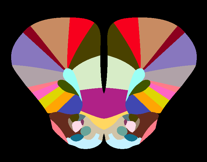
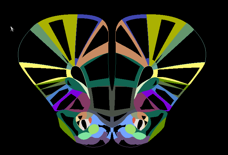
but the result is broken:
... when I compare my annotation file to the annotation file in your example:
My:
Yours:
I think the main difference is that your annotation file uses a signed symmetrical color scheme. Is this really necessary?
In protocol 5 you're not mentioned this:
The text was updated successfully, but these errors were encountered: