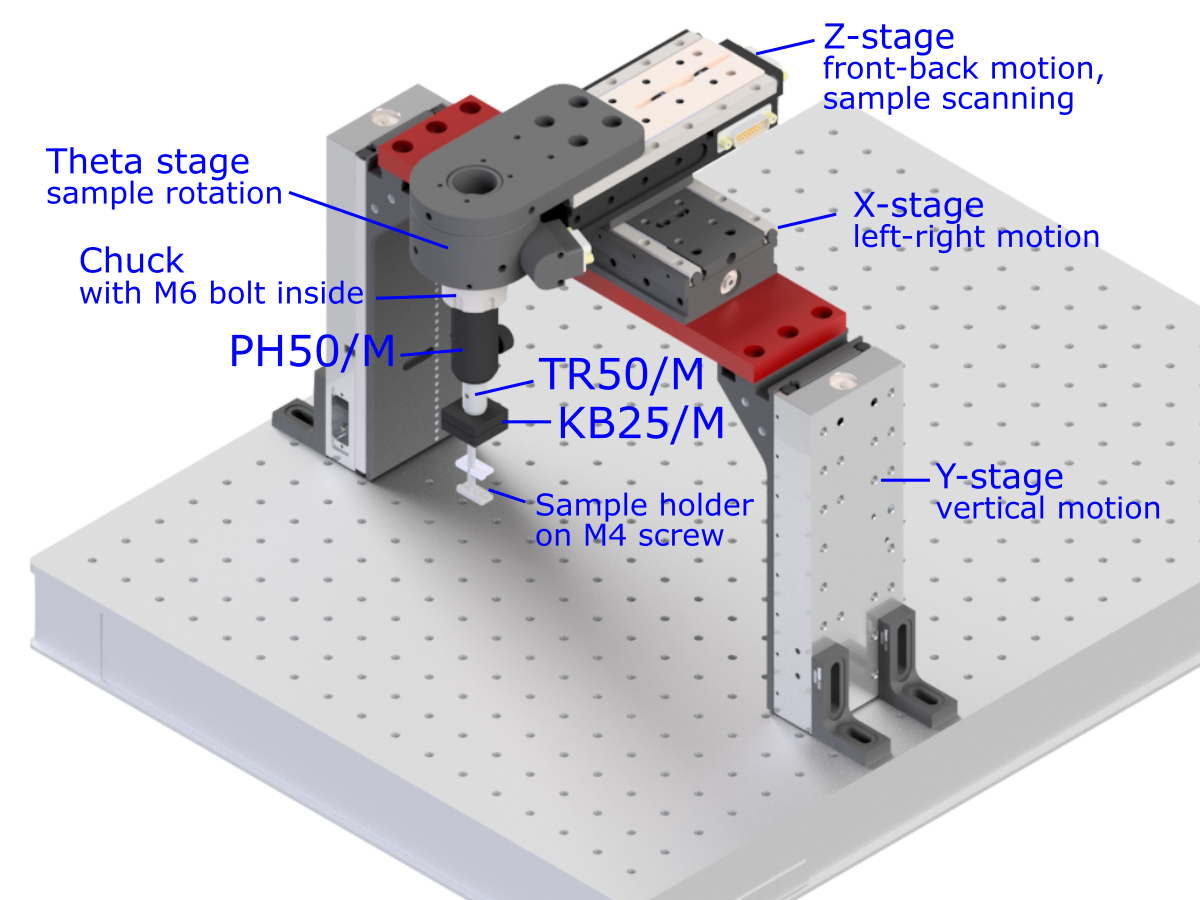
Sample stage assembly
The assembly of sample stages is straightforward:
- connect the two Y-stages with the custom-made bridge part.
- mount the two Y-stages on the base breadboard with brackets (Thorlabs AB90H). Be careful about the vertical stage alignment to each other when tightening the bolts. If the stages are non-collinear they can get jammed, which will cause a controller error (but nothing fatal). Use ASI-provided plastic washers to allow some "self-alignment" of the stages when screws are tightened.
- mount the X and Z stages on the bridge
- connect the Theta stage to the Z-stage.
⚠️ Use only the (short) M6 bolts supplied by ASI, otherwise you risk a permanent damage of the optical encoder that is right under the mounting holes. - insert an M6 bolt (head forward) into the chuck, and tighten the chuck with ASI-provided key
- mount the post holder PH50/M on the M6 bolt
- insert and tighten post TR50/M in the post holder, with the M4 setscrew side sticking out. Remove the M4 setscrew before this.
- attach the upper part of magnetic base KB25/M (the one with 3 half-spheres) to the M4 hole in the post, using a short M4 screw.
- sample holders (clamps etc) are connected to the lower part of magnetic base (KBB25/M, with 3 nests) with an M4 screw (longer screws are preferred).