Assembly overview
/CAD-model-Inventor/mesoSPIM/renderings/overview/view4/Stack.gif)
The animation above shows you the major modules: detection arm, left excitation arm, right excitation arm, sample stages, and stationary cuvette mount, in suggested assembling sequence. This is only an overview - see the detailed instructions for each module for the latest components and their arrangement.

Laser light from the fiber output is collimated by L1 and then redirected into the electrically tunable lens (ETL). A 1:1 relay (lenses L2, L3) reimages the ETL onto a galvo mirror (M3), which is placed at the back pupil plane of the excitation objective L4 (modified f=50 mm Nikon objective). Scanning the Gaussian beam along one axis generates the light-sheet illumination. Modulation of the ETL optical power displaces the light-sheet axially (left to right), and it is synchronized with the sCMOS camera rolling shutter (ASLM mode). The fold mirrors M1, M2 make the system more compact and allow angular alignment of the laser beam.

/CAD-model-Inventor/mesoSPIM/renderings/excitation/excitation-latest.png) 3D rendering of the excitation arms. Parts that need customization/making in a machine shop are marked red.
3D rendering of the excitation arms. Parts that need customization/making in a machine shop are marked red.
Note: Excitation and detection objectives' optical axes are about 135 mm above the optical table.
The right excitation arm is identical to the left arm.
The laser is directed into one of the arm using internal switching mechanism - a flip mirror inside the laser combiner, which allows the latter to rapidly switch between its two fiber ports.
Detection arm consists of a camera with tube lens, objective, and motorized filter wheel with emission filters.
/CAD-model-Inventor/mesoSPIM/renderings/detection/detection-latest.png) The camera is attached to the lens tube with F-mount adapter. The tube lens mount (red) consists of 3D printed holder on a rail carriage. The motorized filter wheel (blue, Zwo EFW-Mini) has 5 filter slots and accepts standard 25-mm fluorescence filters.
The camera is attached to the lens tube with F-mount adapter. The tube lens mount (red) consists of 3D printed holder on a rail carriage. The motorized filter wheel (blue, Zwo EFW-Mini) has 5 filter slots and accepts standard 25-mm fluorescence filters.

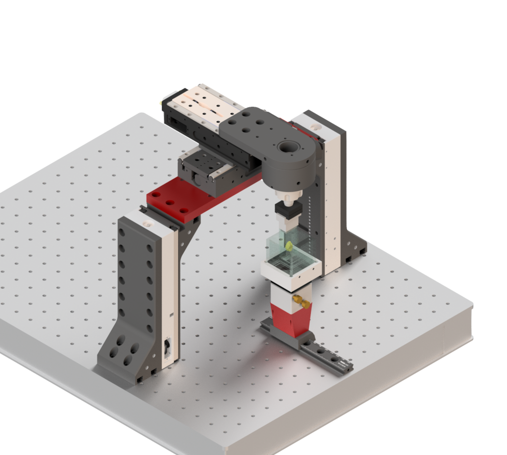
The sample stages assembly consists of two vertical linear stages (Y axis, ASI Dual-LS100-FTP, travel range 100 mm) connected together with a custom bridge (red, ASI mesoSPIM-Bridge). The X- and Z-axis stages are mounted on the bridge, and the rotation stage is mounted on top Z-stage. The sample (green) in a sample cuvette (or holder) is attached to the rotating stage shaft via kinematic base (Thorlabs KB25/M). The immersion cuvette with index-matched oil is placed on adjustable prism table (Radiant Dyes RD-PDT-S).