-
Notifications
You must be signed in to change notification settings - Fork 34
New issue
Have a question about this project? Sign up for a free GitHub account to open an issue and contact its maintainers and the community.
By clicking “Sign up for GitHub”, you agree to our terms of service and privacy statement. We’ll occasionally send you account related emails.
Already on GitHub? Sign in to your account
Clarity needed for Alignment Cant axis of rotation #160
Comments
|
Looks like I can answer my own question based on discussion in the referenced thread. The geometry representation can stand on its own and does not require anything from the business logic. The other two points still stand - another diagram is required to describe rotation about centerline and both diagrams need updated to dimension CantLeft and CantRight that are contained in the business logic. Which then also means another normative rule in the ALA series is required to confirm that the point of rotation described by the representation matches what is described by the values of CantLeft and CantRight in the business logic. |
|
In practice, I think you are right that the point of rotation is at one of the rail heads or at the center point between. However, the semantic and geometry definitions could be used for rotation about any point. Here is a quick sketch to illustrate what I mean. LeftCant, RightCant, and Railhead Distance define slope and point of rotation |
|
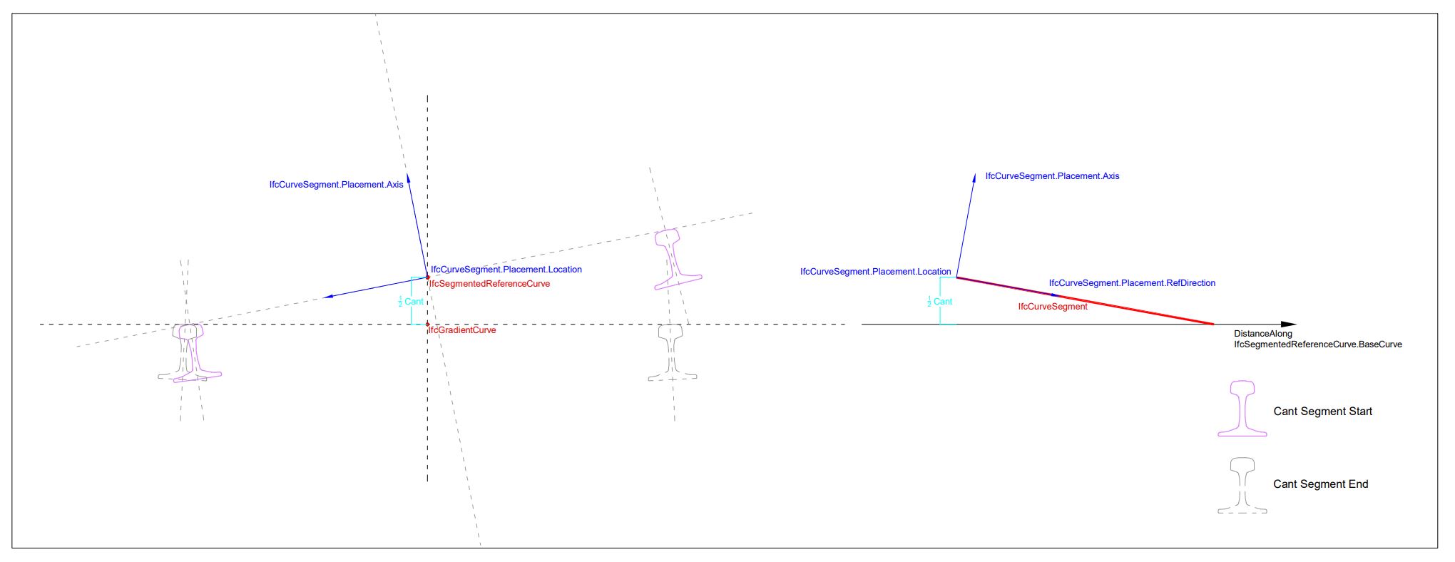
After many sleepless nights trying to figure out cant, I think I've got it. Thanks to everyone who helped me. @evandroAlfieri @civilx64 @peterrdf @jmirtsch @SergejMuhic @aothms I propose the following documentation for IfcSegmentedReferenceCurve. Having an example is not consistent with any other part of the IFC specification, but I think it clarifies in the intent of all the technical speak. My proposal to have the example be part of the Semantic Definition is flexible. If the IFC specification had a commentary, this would be a good place for such an example. Alternatively, the example could go in 8.9.3.62.4 Example 8.9.3.62.1 Semantic DefinitionThe IfcSegmentedReferenceCurve is a curve defined in the linear parameter space of its base curve that is set in the attribute BaseCurve. The base curve provides a basis for the positioning of the collection of IfcCurveSegment occurrences. A deviating explicit position of a curve segment (IfcCurveSegment.Placement) from the axis of the basis curve produces a superelevation (i.e. depression or elevation from the axis of the base curve). The deviating elevation is defined by the IfcCurveSegment.ParentCurve in the linear parameter space of the base curve. If no deviation in the position of the curve segment to the base curve axis is specified, the axes (Axis and RefDirection) directions of IfcAxis2Placement are interpolated between the initial curve segment placement and the placement of the subsequent curve segment. The parameterization of IfcSegmentedReferenceCurve is based on the parameterization of the BaseCurve and is not altered by the Segments. Figure 8.9.3.62.A shows a cross section of a IfcSegmentedReferenceCurve usage for an alignment representation featuring cant with rotation about the low rail and varying superelevation.
Figure 8.9.3.62.B shows a cross section of a IfcSegmentedReferenceCurve usage for an alignment representation feature cant with rotation about the track centerline with no deviating position.
Informally, a IfcSegmentedReferenceCurve is a curve defined in a “horizontal distance along base curve, deviating elevation” coordinate system. The IfcCurveSegment.ParentCurve defines the change in cross slope between rail heads over the length of the segment. When the IfcCurveSegment.Placement.Location differs from the IfcCurveSegmentPlacement.Location of the next segment (or the IfcSegmentedReferenceCurve.EndPoint for the last segment, if specified), the IfcCurveSegment.ParentCurve also defines the deviating elevation. If the IfcCurveSegment.Placement.Location is the same as for the start of the next segment, the deviating elevation along the length of the segment is constant. Evaluation of a IfcCurveSegment that is part of a IfcSegmentedReferenceCurve is illustrated with an example. Consider a IfcCurveSegment with a IfcCosineSpiral parent curve. The curve segment has a position of (0.0,0.08,0.0) and an Axis of (0.0, 0.10606,0.99436). The curve segment has a length of 100. The next curve segment has a position of (100.0,0.0,0.0) and an Axis of (0.0, 0.0,1.0). The constant and cosine terms are both 2500. The parent curve equation is The deviating elevation at the start of the segment is The deviating elevation at the end of the segment is The deviating elevation at the segment mid-point is The orientation of the Axis at the start of the segment is The orientation of the Axis at the end of the segment is The orientation of Axis at the segment mid-point is The slope of the deviating elevation is the derivative of the parent curve. RefDirection = ( The Z-Direction at the segment mid-point is (0.0, The Y-Direction is the cross product of Z-Direction and RefDirection Axis is the cross product of RefDirection and Y-Direction Figure 8.9.3.62.C shows the deviating elevation of the left rail, right rail, and centerline of track along the length of the segment.
Figure 8.9.3.62.D shows the orientation variation of Axis along the length of the segment |
|
That is fantastic! 🚀 Thanks @RickBrice (and all others that contributed to this). |


Problem
Ref buildingSMART/IFC4.3.x-sample-models#23
As I see it there are four variables related to fully describing cant:
Figure 8.9.3.62.A in the docs for IfcSegmentedReferenceCurve illustrates these relationships when the low rail is the point of rotation:

There is no corresponding figure to illustrate how rotation about centerline is to be defined.
Solution(s)
Another graphic illustration for rotation about centerline of rail is needed.
Require schema changes?
✓noRequire documentation changes?
✓yesRule required
✓other normative rule: a normative check of the IFC Validation Service. Every IFC file must pass this checkMy hypothesis is that business logic - specifically IfcAlignmentCantSegment.DesignParameters - must be provided in addition to the IfcCurveSegment representation entity. If true then this should be enforced by a normative rule.
The text was updated successfully, but these errors were encountered: