Home
#A
Quite a bit, actually!
Welcome to the HRT Keypad Contest information page.

Thanks again to Gateway Electronics!
During late 2012, at their work, Mr. S and Mr. O ran across some keypads that were being thrown away. The idea of using the enclosures for a home project was mentioned so eleven of them were salvaged from the trash. Curiosity got the better of Mr. S, and he opened one of them to see what was inside: An 8051-compatible, 20-pin micro-controller, several octal latches, an RS-232 transceiver, a reset component, a crystal, and a bunch of passives.
The idea of reprogramming the 8051-compatible micro-controller was quickly abandoned after realizing the difficulty of developing for such a device. It was noted, however, that the power, ground, and clock pins were in the same position as that of the popular Atmel ATtiny2313. At some point one of them mentioned the idea of having a contest, but doing so would require a programmer for each of the keypads, so nothing serious came of it immediately.
Later that year Mr. S was finishing work on his home-built CNC machine and wanted to try the new machine's ability with milling a PCB. Mr. S came upon the idea of creating programmers for the ATtiny2313 and using those to hold a contest with the keypads retrofitted with an ATtiny2313.
New artwork was created for a single-sided, milled version of the USBtinyISP. The programmers were milled, soldered and tested. The reset device was removed from the keypad's circuit, and the 8051 MCU was replaced with the ATtiny2313.
On December XX, 2012, Mr. S presented a talk to a group of engineers (mostly software engineers) on how to program a micro-controller, how the hardware worked, and details of the contest. The attendees were each offered a development kit at no cost, on the condition that they return the kit if they didn't complete an entry for the contest.
Additionally, Gateway Electronics provided the grand prize for the competition! If you aren't familiar with them, Gateway Electronics (or just "Gateway", as all the cool kids call it) is St. Louis's electronic components, hobbyist, and DIY repair supplies retail store. Located in the Westport area, you can visit them to find all sorts of components from LEDs, resistors, capacitors, connectors, switches, enclosures, motors, relays, robot parts, and all sorts of wires and cables (pre-made, packaged, by-the-spool, and by-the-foot) to electronics kits, tools, power supplies and test equipment, prototyping supplies, and also an entire section of miscellaneous mystery things--you never know what you'll find when perusing the back aisle!
On January 15, 2013 a meeting was held where a demonstration of the projects occurred. The contest entries have been released as open source and have been made available in this github repository.
Of the original eleven keypads, seven people submitted a complete project.
Bongo Hero is a one person game modeled after the popular guitar game. The game has three user selectable levels of increasing difficulty that are selectable when power is applied. Unlike all the other entries submitted for our contest, Bongo Hero is played with the keypad controller rotated 90 degrees from normal. For gameplay, lights "fall" from button 1 to button 5 for the right "bongo", and from button 6 to 10 for the left "bongo". When the lights reach the bottom row, players must hit the appropriate "bongo" (either button 5 or 10) in time with the lights. When the bongos are hit in tempo, all lights in that row illuminate for 0.1sec to indicate a proper hit. The sequence and tempo for each level are programmed into the software. Level 1 is a basic, slow rhythm. Level 2 is 'Back in Black'. Level 3 is 'Rock and Roll'. After each level completes, the software automatically returns to the level selection menu.
The software is written using timers to control the light progression. This makes controlling tempo extremely easy, and accurate. The sequence of hits is programmed as two separate byte-arrays for each bongo. The sequence is played using nested for-loops, and bit-shift arithmetic. The inner-most for loop continuously reads from the switches until the timer indicates the next note should be played.
The author considered adding two Photo-Trasistors and Infrared LEDs to the side of the device in order to sense hand movement using an actual set of bongos, but ultimately, it was decided that he wasn't getting paid enough for that.
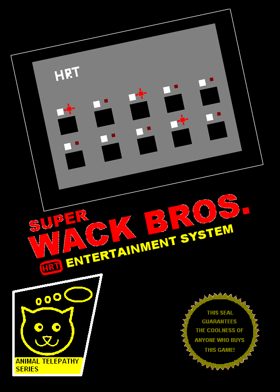
Super Wack Bros. is a two-player head-to-head super-wack whack-a-mole game. The players each have to guard four mole holes, and win by getting ahead of their opponent by reacting the fastest. The game can use the optional speaker to play sound effects and in-game music inspired by music from the classic Dig-Dug game. As the game progresses the game play and music speed-up, increasing the tension.
The slides of the presentation given during the demo can be seen here.
A video demonstration can be seen here.
Box art inspired by the Nintendo Entertainment System's launch game series, commonly called the black box games: Front and Back
The fuses default to the built in 8Mhz oscillator and divide that clock by 8 for a CPU clock rate of 1MHz. The fuses can be reset to start up at a faster clock rate, or the software can reset the clock divider.
If you have an updated repository with the cpu_clock sample and header,
#include "../../include/ATtiny2313_clock.h"
int main()
{
        CPU_PRESCALE(inline_cpu_hz_to_prescale(F_CPU));
}
Otherwise, for 8MHz,
#define CPU_PRESCALE(n) \
{uint8_t __read_hz=n; CLKPR = _BV(CLKPCE); CLKPR = __read_hz;}
int main()
{
        CPU_PRESCALE(0)
}
Either way the cost is 6 bytes of program code.
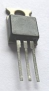
Attention: Did you remove the ribbon cable from the main board of the keypad and forget it's correct orientation for reattachment? Wire #1 (the one with the red stripe on it) is closest to the MCU. Wire #10 (the wire on the opposite edge of the ribbon cable from the red one) is closest to the TO-220 voltage regulator.
Requires:
- Soldering iron, solder and basic soldering skills
- DC power jack
- Drill and bit
- A tools to cut and strip wire
- Spare AC adapter
- Tape
An AC adapter can be used instead of a battery. One way to do it is to drill a hole in the back cover plate for a DC power jack 
Requires:
- Soldering iron, solder and basic soldering skills
- A female DB-9 connector (or sacrifice the provided 9V power supply)
- Maybe tools to cut and strip wire
- A small speaker (electromagnetic voice coil or piezo-electric)
- Epoxy if you want to get fancy
Audio can be played with a speaker add-on connected through the DB-9 port. One way to do it is to solder an audio transducer directly to pins 3 and 4 of a female DB-9 connector.
Important note: If you try this, either remove the power jumper from the USBtinyISP programmer, or remove the external power from the keypad (whether that be a 9V battery or an AC adapter).
Note: The author has only tried this with an STK500 programmer, and has not tried this with a USBtinyISP programmer (the type of programmer supplied with the dev kit. If you try this and it works, be sure to note that here. That being said, the author guesses that the USBtinyISP will be able to program the keypad in-circuit.
The advantage of in-system programming is simple for the keypad: You don't have to pull the MCU out of the keypad and insert it into the programmer to program it and then pull it back out of the programmer and put it back in the keypad to test it.
In-system programming can be done in at least two different ways:
-
Buy (no, they aren't cheap) or pull out of the trash, a chip test clip
.
- Solder wires directly to the MCU. If doing this, solder the wires to the top of the necessary pins, and do it with the MCU on it back (pins sticking up) to discourage the solder from flowing towards the tips of the pins as you're going to then put the MCU back in its original socket. As for which pins, I'll leave that as an exercise for the reader, but if you look at the target board, you are going to be copying that.
 .
.
It was mentioned that the acid in fingerprints can speed oxidation of the copper plate. Two solutions were presented, one was getting a case for the programmer. For the other clear coat was mentioned. I did the clear coat with some spray paint enamel I had on hand. Here are the before and after shots. Just before I used some rubbing alcohol on a cotton ball (which left fuzz behind), and then used a patch of denim with distilled water, and an air compressor to try to get the fuzz off and dried it. I'm not sure how recommended that procedure is. I covered the holes with tape from the top, then covered the entire top with tape. I did two layers 1/2 day apart, then let it sit for two days and it still works. The bottom looks very nice and sharp. The top not so much, I haven't decided if the paint leaked in just through the tape or if it came in through the holes in the circuit board, and probably both, so it looks a little sloppy, but that bottom sure looks good.
