PID settings wrong #221
Comments
|
I’m confused, I’d say the “original PID code of controller” is non-existent (I couldn’t see any trace of PID going on in the original firmware, that was a straight-up bang-bang controller). But the (supposedly) improved firmware in this repo looks like this last time I checked:
https://github.com/UnifiedEngineering/T-962-improvements/blob/master/src/reflow.c#L155-L175 <https://github.com/UnifiedEngineering/T-962-improvements/blob/master/src/reflow.c#L155-L175>
Note that the T-962-improvements code uses PID output limits that includes both the heating and cooling region, hence 255+248 where the output value of 248 means that neither heating nor cooling is active.
… On 7 Jan 2022, at 10:44, Sevstels ***@***.***> wrote:
The original PID code of the controller does not work correctly due to errors in the settings. It goes into "relay control" mode with a small linear section.
//Heater PWM modulator have range 0...255
del-> PID_SetOutputLimits(pid, 0, 0xffff); <-integrator will overflow here
PID_SetOutputLimits(pid, 0, 0xff); <-correct value
//default Controller Sample Time is 0.1 seconds
del-> SampleTime = 100; <- wrong sampling rate
pid->SampleTime = 250; //250ms loop sample perod
—
Reply to this email directly, view it on GitHub <#221>, or unsubscribe <https://github.com/notifications/unsubscribe-auth/AAYSRDYEA335KRYLEMIKKXTUU2YXLANCNFSM5LOMZPNA>.
Triage notifications on the go with GitHub Mobile for iOS <https://apps.apple.com/app/apple-store/id1477376905?ct=notification-email&mt=8&pt=524675> or Android <https://play.google.com/store/apps/details?id=com.github.android&referrer=utm_campaign%3Dnotification-email%26utm_medium%3Demail%26utm_source%3Dgithub>.
You are receiving this because you are subscribed to this thread.
|
That was not the correct my translation to eng.
In my opinion, the system will work properly if the integral component does not have an offset relative to zero. |
|
In any case. The PID coefficients are is not correct.
Consider the simplest case where only the channel P is used. For example we need to go from 30 degrees to 130 degrees. The delta is 100. With such wrong coefficients, the system goes into "relay control" mode like an ordinary toggle switch. It will oscillate all the time due to loss of stability in the control loop due to excessive loop gain. See the theory of automatic control systems. For example the Nyquist stability criterion. |
|
You only need enough power to make up for the losses in the oven that gets you to 200C. But this says nothing of the time it takes to get there. You would be better with maybe 1800W of power to reach the temperature in a more reasonable period of time. So I'm not sure why you base anything on the power you think is required to reach a certain temperature, as this isn't really all that important. It is more about the power required to get you there in a given period of time. These ovens are generally underpowered, so usually you want the elements to be turned on hard at the start to decrease the risetime, and then back off as the setpoint is reached so as to not overshoot. Planning for a reduced heating rate from the start makes no sense at all. Overflow of the calculations is generally handled by saturating the output value, as in if it is over 255, then force it to 255. It is not the same as relay control, since as the temperature approaches the setpoint, the value will be reduced, so with a 10 degree differential, the output value is now 200, and keeps reducing as you get closer to the setpoint. Whether a gain of 20 would be too high or not would need to be determined through measurements. Also note that strictly proportional control is not what it used, and the I and D terms also play into the equation to help control overshoots, and oscillations. In general, strictly proportional control will never reach the desired setpoint, as you need some output to keep the heaters on to maintain temperature, so the I term at a minimum is requires as well as P. It is the I term that is accumulated due to the error that gives sufficient output to maintain a given temperature. |
|
Anyway. The theory of automatic control systems has long been developed and is explained in detail in universities. The loop gain cannot be more than 1. Otherwise the system loses stability. This mathematics is correct and works even in another galaxy. At an overload of 13 units the stove will ALWAYS WORK WRONG. |
|
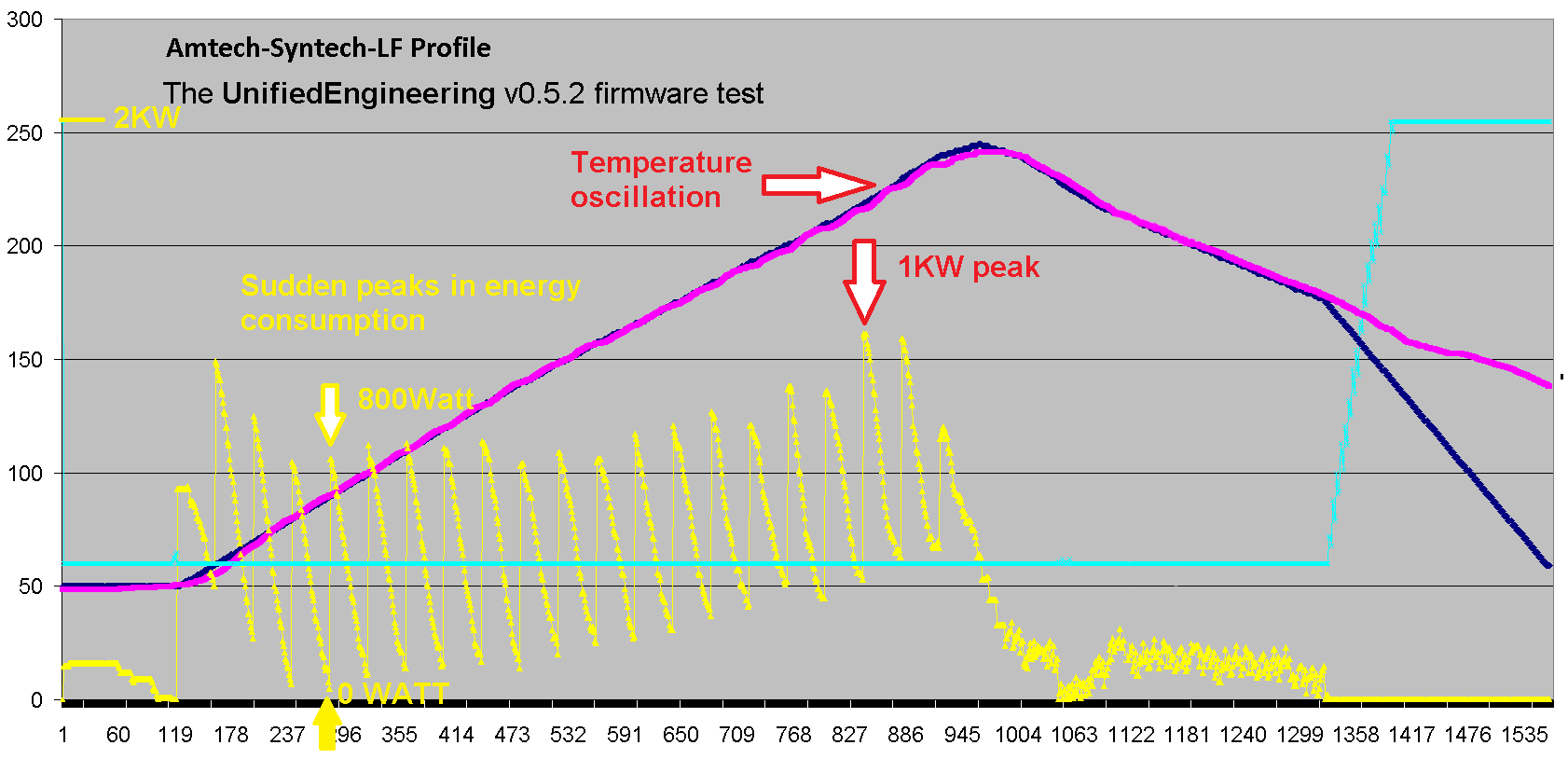
I took some extra time and compared the quality of the firmware and made short conclusions. Two versions were compared: The operation of the v0.5.2 firmware, due to code errors, is probably a danger to your electrical network due to nearly 1 kilowatt spikes in power consumption. This can cause overheating of conductors and connectors and cause a fire. As I wrote above, due to errors in PID settings - the temperature inevitably oscillates. Thank you for your attention. |
|
The large oven I have here toggles between ~0 and over 2kW in pulses. That’s not the PID regulator itself causing that, it’s simply because the PWM is so slow (must be significantly slower than line frequency as there’s no zero-cross detector available). If the heaters could be phase-cut dimmed reliably it would be much better in terms of smoother power consumption, but as the ovens are under-powered it spends most of the time in 100% heating anyway. Some of the opto-diacs (and some solid-state relays) used in certain ovens seems to be of the “only triggger at zero-crossing” variety as well, requiring replacement if phase-cut dimming is to be used. The idea was to support an oven with minimal modifications, which is why the PWM frequency is so slow. I got very inconsistent results when trying to speed that up.
That being said, yes the PID tuning is _poor_, because the system spends most of the time in saturation (due to the oven being under powered). I got to a reasonable result but there’s always room for improvement. Also different size ovens (and variations between otherwise identical ovens) makes constant values less than ideal. Maybe adopting auto PID tuning from Marlin or similar could work?
… On 1 Mar 2022, at 07:47, Sevstels ***@***.***> wrote:
I took some extra time and compared the quality of the firmware and made short conclusions.
You can see the results graphically.
Two versions were compared:
UnifiedEngineering v0.5.2 <https://gradient-sg.com/images/t962/v052-test.png>
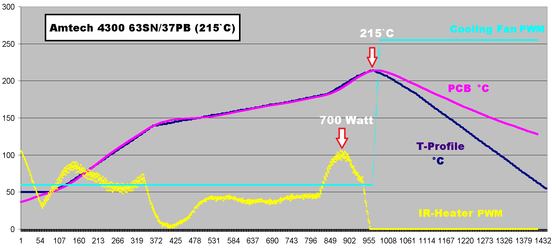
S3D v0.6 regular <https://gradient-sg.com/images/t962/amtech-430.png>
The operation of the v0.5.2 firmware, due to code errors, is probably a danger to your electrical network due to nearly 1 kilowatt spikes in power consumption. This can cause overheating of conductors and connectors and cause a fire. As I wrote above, due to errors in PID settings - the temperature inevitably oscillates. Thank you for your attention.
—
Reply to this email directly, view it on GitHub <#221 (comment)>, or unsubscribe <https://github.com/notifications/unsubscribe-auth/AAYSRDYQTYQWV3A4LB2DYKTU5W4QZANCNFSM5LOMZPNA>.
Triage notifications on the go with GitHub Mobile for iOS <https://apps.apple.com/app/apple-store/id1477376905?ct=notification-email&mt=8&pt=524675> or Android <https://play.google.com/store/apps/details?id=com.github.android&referrer=utm_campaign%3Dnotification-email%26utm_medium%3Demail%26utm_source%3Dgithub>.
You are receiving this because you commented.
|
|
The lack of zero crossing detector gives a maximum irregularity of only a quarter of the power period. Or about +-7 watts. You have an unevenness of about half a kilowatt. When I told you there were errors in the firmware, you didn't want to discuss it and laughed. Even if you fine tune the PID, the ripple in the power supply will remain. Only the fine sinusoidal oscillation will disappear. You should revise your code again to fix this. Cosmetic "improvements" will not help. For example, the S3D version runs on scmRTOS, which already gives significant advantages and stability in the execution of regulation. |
|
Sev, do you understand how PWM works and how it varies the average power delivered to the load?. I'm pleased to say my oven also toggles between 0 and 2.xkW just as it should.
That is incorrect. As long as the rms load is within the rated value of the supply, it is fine. No fault, by law here, may damage cable or infrastructure, the fuse or circuit breaker at the distribution box must protect the cable and installation. A typical 3kW domestic outlet here will happily pulse between 0 and 3kW day and night. I don't know which oven you have, but mine switches the heating elements with a solid state relay which has zero crossing switching. |
|
It's all theory... how and what should be clear to everyone. But in real life it is the opposite. At least because there is oxygen in the atmosphere and there is continuous oxidation of the contacts. That's why there are fires... I hope you will not deny the presence of oxygen and oxidation. In addition to your solid state relay, there are a significant number of connections and contacts in the circuit up to the power distribution station. These contacts or strands have a surface connection resistance and will heat up. And by creating a serious current ripple in this circuit you inevitably provoke a catastrophe. |
//Heater PWM modulator have range 0...255
del: PID_SetOutputLimits(pid, 0, 0xffff); <-wrong limit
PID_SetOutputLimits(pid, 0, 0xff);
//default Controller Sample Time is 0.1 seconds
del: SampleTime = 100; <- wrong sampling rate
pid->SampleTime = 250; //250ms loop sample perod
The text was updated successfully, but these errors were encountered: