RaspberryPi ATX power supply controlled by an ATtiny45.
It is supposed to use a LED button as the main switch. Once the button is pressed for more than 0.5 seconds the ATX power supply is turned on by the MCU, which is indicated by the button's LED, and the RaspberryPi (which is connect to a non-standby 5V line - see http://reprap.org/wiki/PC_Power_Supply) will start booting. In the end of the startup sequence a tiny Python script is started which sets a certain GPIO-pin to "high" to tell the MCU that the RaspberryPi is running. Afterwards the script is waiting for on another GPIO-pin for the signal to shut down which is sent by the MCU once the button is pressed again for more than 0.5 seconds. If so the Python script calls "poweroff" which shuts down the RaspberryPi. At the end of shutting down the "running" indicator GPIO-pin goes to "low" what is recognized by the MCU which turns off the ATX power supply after 0.5 seconds (to be sure it is safe to power off).
If the RaspberryPi is running and the button is pressed for more than 5 seconds then the ATX power supply is turned off immediately. Don't use this feature during SD card activity because it may break your SD card!
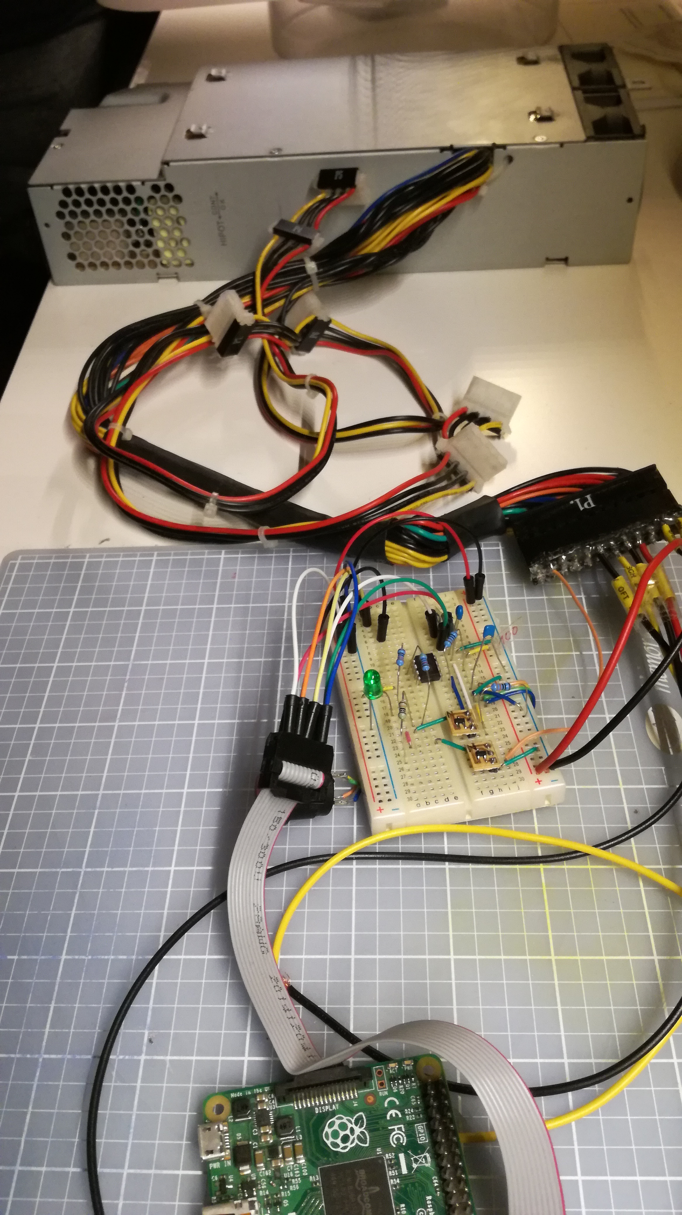
See the breadboard version in action: https://youtu.be/JrYkC-bjguw

-
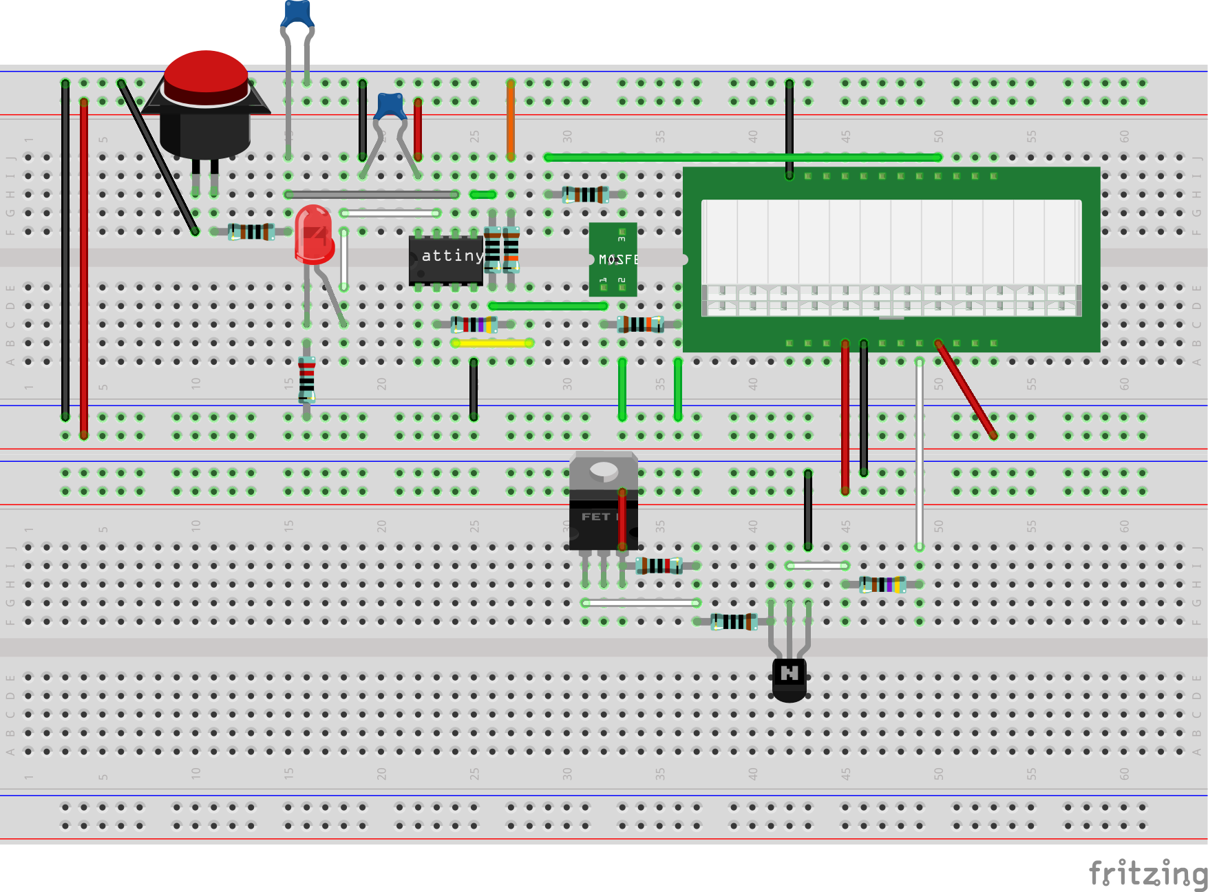
I used a simple RC filter for button debouncing. This is sufficient because the MCU is running at a low frequency (128kHz). I removed the 10k resistor of the RC filter which is replaced by the MCU's pull-up resistor.
-
For some ATX power supplies it is necessary to provide a base load. Everything is fine if your ATX wants this load on the 5V line because the RaspberryPi is the load. My ATX wants the load on the 3.3V line, so I had to add a 22 Ohm ceramic 5W resistor which builds a load of 150mA. There is a place for this resistor on the PCB.
-
I tested the curcuit using two different ATX power suppliers. As mentioned above the first wants a base load on the 3.3V line. For the second it was necessary to protect the "power on" line (see chapter "ATX lines") by a 1k Ohm current limiting resistor (R10). For the first it was OK to simply pull this line down. Additionally the second power supply did not require a base load resistor as long the current limiting resistor was not to big. The voltage of that line is 2.7V (for this certain power supply) and a 1k Ohm resistor means 2.7mA. You may need to vary this value according to your power supply.
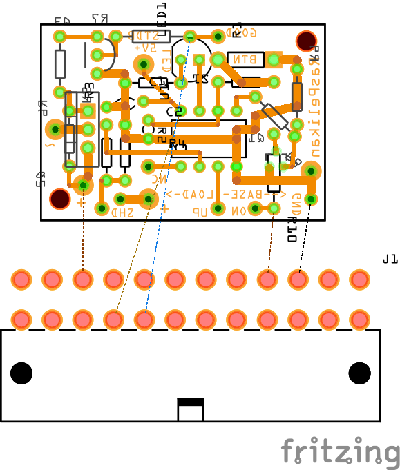
This is an etchable PDF and the Fritzing file.
- black: GND - connect this to the PCB and the RaspberryPi
- red: 5V+ - connect this to the RaspberryPi
- orange: 3.3V+
- yellow: 12V+
- green: power on - connect this to the PCB
- gray: power good - connect this to the PCB
- purple: 5V+ standby - connect this to the PCB
Use different ground lines for the PCB, the RaspberryPi and for other consumers connected to the ATX power supply. This is necessary to distribute the load to several lines to prevent cable damages. The RaspberryPi and the PCB do not consume so much current but you may connect further consumers as well (otherwise it would be an overkill to run a RaspberryPi by an ATX power supply).
Copy the file
src/main/python/shutdown.py
to your RaspberryPi. You may place it in the system's etc folder by using this command
sudo cp shutdown.py /etc/
and make it runnable
sudo chmod a+x /etc/shutdown.py
The script has to be added at the end of the boot sequence by editing the file
/etc/rc.local
Add the line
/etc/shutdown.py &
before the line
exit 0
Once this is done you have to reboot. Login again and you will see the script running by
ps -ef | grep shutdown
In the script the lines
ON_INDICATOR_GPIO=23
SHUTDOWN_GPIO=24
are used to define which GPIO-pins of the RaspberryPi are connected to the MCU for controlling the shutdown. Use this pinout to find the GPIO-pins 23 and 24 or choose other numbers for your RaspberryPi.
For writing the software to the MCU you will need a programmer. I use an USBasp programmer. I use this chinese clone which works pretty good and additionally has all lines to be updated to USBasp+. The Makefile is meant to run on a Linux compatible system with avr-gcc and avrdude installed on it.
Build the software by the command
make deploy
Reading the current fuses is supported by the command
make readfuses
The right fuses can be set by the command
make writefuses
Hint: Once the fuses are written the MCU runs at 128kHz which means that you have to turn on the "slow"-mode of your USBasp programmer by shortening the JP2 (or JP3 for those chinese clones which have an extra jumper for 3.3V support). Otherwise the MCU won't be detected any more by the programmer.