![]()
Crest is a technically-advanced ocean system for Unity. It is architected for performance and makes heavy use of Level Of Detail (LOD) strategies and GPU acceleration for fast update and rendering. It is also highly flexible and allows any custom input to the water shape/foam/dynamic waves/etc, and has an intuitive and easy to use shape authoring interface.
A video walkthrough of the setup steps below is available on youtube: https://www.youtube.com/watch?v=qsgeG4sSLFw .
Note: Frequently when changing Unity versions the project can appear to break (no ocean rendering, materials appear pink, other issues). Usually restarting the Editor fixes it. In one case the scripts became unassigned in the example content scene, but closing Unity, removing the Library folder, and restarting resolved it.
The steps to set up Crest in a new or existing project currently look as follows:
- Switch to Linear space rendering under Edit/Project Settings/Player/Other Settings. If your platform(s) require Gamma space, the material settings will need to be adjusted to compensate.
- Import Crest assets by either:
- Picking a release from the Releases page and importing the desired packages
- Getting latest by either cloning this repos or downloading it as a zip, and copying the Crest/Assets/Crest/Crest folder and the desired content from the nearby Crest-Examples folders into your project. Be sure to always copy the .meta files.
The steps to set up the ocean:
- Create a new game object for the ocean
- Assign the OceanRenderer component to it. On startup this component will generate the ocean geometry and do all required initialisation.
- Assign the desired ocean material to the OceanRenderer script - this is a material using the Crest/Ocean shader.
- Set the Y coordinate of the position to the desired sea level.
- Tag a primary camera as MainCamera if one is not tagged already, or provide the Viewpoint transform to the OceanRenderer script. If you need to switch between multiple cameras, update the Viewpoint field to ensure the ocean follows the correct view.
- To add waves, create a new GameObject and add the Shape Gerster Batched component.
- On startup this script creates a default ocean shape. To edit the shape, right click in the Project view and select Create/Crest/Ocean Wave Spectrum and provide it to this script.
- Smooth blending of ocean shapes can be achieved by adding multiple Shape Gerstner Batched scripts and crossfading them using the Weight parameter.
- For geometry that should influence the ocean (attenuate waves, generate foam):
- Static geometry should render ocean depth just once on startup into an Ocean Depth Cache - the island in the main scene in the example content demonstrates this.
- Dynamic objects that need to render depth every frame should have a Register Sea Floor Depth Input component attached.
- Be sure to generate lighting from the Lighting window - the ocean lighting takes the ambient intensity from the baked spherical harmonics.
- Ocean material / shading: The default ocean materials contain many tweakable variables to control appearance. Turn off unnecessary features to maximize performance.
- Animated waves / ocean shape: Configured on the ShapeGerstnerBatched script by providing an Ocean Wave Spectrum asset. This asset has an equalizer-style interface for tweaking different scales of waves, and also has some parametric wave spectra from the literature for comparison.
- Ocean foam: Configured on the OceanRenderer script by providing a Sim Settings Foam asset.
- Dynamic wave simulation: Configured on the OceanRenderer script by providing a Sim Settings Wave asset. For more information see the Dynamic Waves section below.
- A big strength of Crest is that you can add whatever contributions you like into the system. You could add your own shape or deposit foam onto the surface where desired. Inputs are generally tagged with the Register scripts and examples can be found in the example content scenes.
All settings can be live authored. When tweaking ocean shape it can be useful to freeze time (set Time.timeScale to 0) to clearly see the effect of each octave of waves.
Reflections contribute hugely to the appearance of the ocean. The Index of Refraction settings control how much reflection contributes for different view angles.
The base reflection comes from a one of these sources:
- Unity's specular cubemap. This is the default and is the same as what is applied to glossy objects in the scene. It will support reflection probes, as long as the probe extents cover the ocean tiles, which enables real-time update of the reflection environment (see Unity documentation for more details).
- Override reflection cubemap. If desired a cubemap can be provided to use for the reflections. For best results supply a HDR cubemap.
- Procedural skybox - developed for stylized games, this is a simple approximation of sky colours that will give soft results.
This base reflection can then be overridden by dynamic planar reflections. This can be used to augment the reflection with 3D objects such as boat or terrain. This can be enabled by applying the Ocean Planar Reflections script to the active camera and configuring which layers get reflected (don't include water). This renders every frame by default but can be configured to render less frequently. This only renders one view but also only captures a limited field of view of reflections, and the reflection directions are scaled down to help keep them in this limited view, which can give a different appearance. Furthermore 'planar' means the surface is approximated by a plane which is not the case for wavey ocean, so the effect can break down. This method is good for capturing local objects like boats etc.
A good strategy for debugging the use of Unity's specular cubemap is to put another reflective/glossy object in the scene near the surface, and verify that it is lit and reflects the scene properly. Crest tries to use the same inputs for lighting/reflections, so if it works for a test object it should work for the water surface as well.
There are just two parameters that control the construction of the ocean shape and geometry:
- Lod Data Resolution - the resolution of the various ocean LOD data including displacement textures, foam data, dynamic wave sims, etc. Sets the 'detail' present in the ocean - larger values give more detail at increased run-time expense.
- Geometry Down Sample Factor - geometry density - a value of 2 will generate one vert per 2x2 LOD data texels. A value of 1 means a vert is generated for every LOD data texel. Larger values give lower fidelity surface shape with higher performance.
- Lod Count - the number of levels of detail / scales of ocean geometry to generate. The horizontal range of the ocean surface doubles for each added LOD, while GPU processing time increases linearly. It can be useful to select the ocean in the scene view while running in editor to inspect where LODs are present.
- Wind direction angle - this global wind direction affects the ocean shape
- Max Scale - the ocean is scaled horizontally with viewer height, to keep the meshing suitable for elevated viewpoints. This sets the maximum the ocean will be scaled if set to a positive value.
- Min Scale - this clamps the scale from below, to prevent the ocean scaling down to 0 when the camera approaches the sea level. Low values give lots of detail, but will limit the horizontal extents of the ocean detail.
A typical render order for a frame is the following:
- Opaque geometry is rendered, writes to opaque depth buffer (queue <= 2500)
- Sky is rendered, probably at zfar with depth test enabled so it only renders outside the opaque surfaces
- Frame colours and depth are copied out for use later in postprocessing
- Ocean 'curtain' renders, draws underwater effect from bottom of screen up to water line (queue = 2510)
- It is set to render before ocean in UnderwaterEffect.cs
- Sky is at zfar and will be fully fogged/obscured by the water volume
- Ocean renders early in the transparent queue (queue = 2510)
- It samples the postprocessing colours and depths, to do refraction
- It reads and writes from the frame depth buffer, to ensure waves are sorted correctly
- It stomps over the underwater curtain to make a correct final result
- It stopms over sky - sky is at zfar and will be fully fogged/obscured by the water volume
- Particles and alpha render. If they have depth test enabled, they will clip against the surface
- Postprocessing runs with the postprocessing depth and colours
The Animated Waves simulation contains the animated surface shape. This typically contains the ocean waves, but can be modified as required. For example parts of the water can be pushed down below geometry if required.
The animated waves sim can be configured by assigning an Animated Waves Sim Settings asset to the OceanRenderer script in your scene (Create/Crest/Animated Wave Sim Settings). The waves will be dampened/attenuated in shallow water if a Sea Floor Depth LOD data is used (see below). The amount that waves are attenuated is configurable using the Attenuation In Shallows setting.
Crest supports adding custom shape to the water surface. To add some shape, add some geometry into the world which when rendered from a top down perspective will draw the desired displacements. Then assign the RegisterAnimWavesInput script which will tag it for rendering into the shape, and apply a material with a shader of type Crest/Inputs/Animated Waves/.... This is demonstrated in this tutorial video: https://www.youtube.com/watch?v=sQIakAjSq4Y.
There is an example in the boat.unity scene, gameobject wp0, where a smoothstep bump is added to the water shape. This is an efficient way to generate dynamic shape. This renders with additive blend, but other blending modes are possible such as alpha blend, multiplicative blending, and min or max blending, which give powerful control over the shape.
This LOD data is a multi-resolution dynamic wave simulation, which gives dynamic interaction with the water. To turn on this feature, enable the Create Dynamic Wave Sim option on the OceanRenderer script.
One use case for this is boat wakes. In the boat.unity scene, the geometry and shader on the WaterObjectInteractionSphere0 will render forces into the sim. It has the RegisterDynWavesInput script that tags it as input.
After the simulation is advanced, the results are converted into displacements and copied into the displacement textures to affect the final ocean shape. The sim is added on top of the existing Gerstner waves.
Crest supports adding forces into the sim to perturb the waves. To add a force, add some geometry into the world which when rendered from a top down perspective will draw the desired forces. Then assign the RegisterDynamicWavesInput script which will tag it for rendering into the shape, and apply a material with a shader of type Crest/Inputs/Dynamic Waves/.... The process for adding inputs is demonstrated in this tutorial video: https://www.youtube.com/watch?v=sQIakAjSq4Y.
An example can be found in the boat prefab. Each LOD sim runs independently and it is desirable to add interaction forces into all appropriate sims. The ObjectWaterInteraction script takes into account the boat size and counts how many sims are appropriate, and then weights the interaction forces based on this number, so the force is spread evenly to all sims. As noted above, the sim results will be copied into the dynamic waves LODs and then accumulated up the LOD chain to reconstruct a single simulation.
The dynamic waves sim can be configured by assigning a Dynamic Wave Sim Settings asset to the OceanRenderer script in your scene (Create/Crest/Dynamic Wave Sim Settings).
This is the recommended workflow for configuring the dynamic wave simulation. All of the settings below refer to the Dynamic Wave Sim Settings.
- Set the Gravity Multiplier to the lowest value that is satisfactory. Higher values will make the simulated waves travel faster, but make the simulation more unstable and require more update steps / expense.
- Increase Damping as high as possible. Higher values make the sim easier to solve, but makes the waves fade faster and limits their range.
- Set the Courant Number to the highest value which still yields a stable sim. Higher values reduce cost but reduce stability. Put the camera low down near the water while testing as the most detailed waves are the most unstable.
- Reduce Max Sim Steps Per Frame as much as possible to reduce the simulation cost. This may slow down waves in the lower LOD levels, which are the most detailed waves. Hopefully this slight slow down in just the smallest wavelengths is not noticeable/objectionable for the player. If waves are visible travelling too slow, increase it.
The OceanDebugGUI script gives the debug overlay in the example content scenes and reports the number of sim steps taken and sim step dt at each frame.
The Foam LOD Data is simple type of simulation for foam on the surface. Foam is generated by choppy water (specifically when the surface is pinched). Each frame, the foam values are reduced to model gradual dissipation of foam over time.
To turn on this feature, enable the Create Foam Sim option on the OceanRenderer script, and ensure the Enable option is ticked in the Foam group on the ocean material.
Crest supports inputing any foam into the system. To add some shape, add some geometry into the world which when rendered from a top down perspective will generate the desired foam values. Then assign the RegisterFoamInput script which will tag it for rendering into the shape, and apply a material with a shader of type Crest/Inputs/Foam/.... The process for adding inputs is demonstrated in this tutorial video: https://www.youtube.com/watch?v=sQIakAjSq4Y.
The foam sim can be configured by assigning a Foam Sim Settings asset to the OceanRenderer script in your scene (Create/Crest/Foam Sim Settings). There are also parameters on the material which control the appearance of the foam.
This LOD data provides a sense of water depth. More information about how this is used is in the Shorelines and shallow water section below.
This data drives clipping of the ocean surface, as in carving out holes. This can be useful for hollow vessels or low terrain that goes below sea level. Data can come from geometry, convex hulls or a texture. The system can also be configured to clip everything by default and include only where needed which is useful if water is only required in limited area(s), and this use case is described below.
To turn on this feature, enable the Create Clip Surface Data option on the OceanRenderer script, and ensure the Enable option is ticked in the Clip Surface group on the ocean material.
The data contains 0-1 values. Holes are carved into the surface when the values is greater than 0.5.
Overlapping meshes will not work correctly in all cases. There will be cases where one mesh will overwrite another resulting in ocean surface appearing where it should not. Overlapping boxes aligned on the axes will work well whilst spheres may have issues.
Clip areas can be added by adding geometry that covers the desired hole area to the scene and then assigning the RegisterClipSurfaceInput script. See the FloatingOpenContainer object in the boat.unity scene for an example usage.
To use other available shaders like ClipSurfaceRemoveArea or ClipSurfaceRemoveAreaTexture: create a material, assign to renderer and disable Assign Clip Surface Material option. For the ClipSurfaceRemoveArea shaders, the geometry should be added from a top down perspective and the faces pointing upwards.
The system can be configured to clip everything by default and include water only where needed, which is useful if water is only required in limited area(s). This is configured by the Default Clipping State setting on the OceanRenderer component. It can be set to Everything Clipped and then a clipping input with shader type Crest/Inputs/Clip Surface/Include Area will include areas of water.
As a final feature, the Clip Below Terrain toggle on the ocean material will clip the surface underneath the land. Note that this works purely from a depth cache and does not required the Create Clip Surface Data option enabled on the OceanRenderer component and is therefore more efficient.
To enable shadowing of the ocean surface, data is captured from the shadow maps Unity renders. These shadow maps are always rendered in front of the viewer. The Shadow LOD Data then reads these shadow maps and copies shadow information into its LOD textures.
To turn on this feature, enable the Create Shadow Data option on the OceanRenderer script, and ensure the Shadowing option is ticked on the ocean material.
It stores two channels - one channel is normal shadowing, and the other jitters the lookup and accumulates across many frames to blur and soften the shadow data. The latter channel is used to affect scattered light within the water volume.
The shadow sim can be configured by assigning a Shadow Sim Settings asset to the OceanRenderer script in your scene (Create/Crest/Shadow Sim Settings). In particular, the soft shadows are very soft by default, and may not appear for small/thin shadow casters. This can be configured using the Jitter Diameter Soft setting.
There will be times when the shadow jitter settings will cause shadows or light to leak. An example of this is when trying to create a dark room during daylight. At the edges of the room the jittering will cause the ocean on the inside of the room (shadowed) to sample outside of the room (not shadowed) resulting in light at the edges. Reducing the Jitter Diameter Soft can solve this, but we have also provided a Register Shadow Input component which can override shadow data. This component bypasses jittering and gives you full control.
Currently in the built-in render pipeline, shadows only work when the primary camera is set to Forward rendering.
Flow is the horizontal motion of the water volumes. It is used in the whirlpool.unity scene to rotate the waves and foam around the vortex. It does not affect wave directions, but transports the waves horizontally. This horizontal motion also affects physics.
To turn on this feature, enable the Create Flow Sim option on the OceanRenderer script, and ensure the Flow option is ticked on the ocean material.
Crest supports adding any flow velocities to the system. To add flow, add some geometry into the world which when rendered from a top down perspective will draw the desired displacements. Then assign the RegisterFlowInput script which will tag it for rendering into the flow, and apply a material with a shader of type Crest/Inputs/Flow/.... The Crest/Inputs/Flow/Add Flow Map shader writes a flow texture into the system. It assumes the x component of the flow velocity is packed into 0-1 range in the red channel, and the z component of the velocity is packed into 0-1 range in the green channel. The shader reads the values, subtracts 0.5, and multiplies them by the provided scale value on the shader. The process of adding ocean inputs is demonstrated in the following video: https://www.youtube.com/watch?v=sQIakAjSq4Y.
To add waves, add the ShapeGerstnerBatched component to a GameObject.
The appearance and shape of the waves is determined by a wave spectrum. A default wave spectrum will be created if none is specified. To change the waves, right click in the Project view and select Create/Crest/Ocean Wave Spectrum, and assign the new asset to the Spectrum property of the ShapeGerstnerBatched script.
The spectrum has sliders for each wavelength to control contribution of different scales of waves. To control the contribution of ~2m wavelengths, use the slider labelled '2'.
The Wave Direction Variance controls the spread of wave directions. This controls how aligned the waves are to the wind direction.
The Chop parameter scales the horizontal displacement. Higher chop gives crisper wave crests but can result in self-intersections or 'inversions' if set too high, so it needs to be balanced.
To aid in tweaking the spectrum values we provide implementations of common wave spectra from the literature. Select one of the spectra by toggling the button, and then tweak the spectra inputs, and the spectrum values will be set according to the selected model. When done, toggle the button off to stop overriding the spectrum.
All of the above can be tweaked in play mode. Together these controls give the flexibility to express the great variation one can observe in real world seascapes.
By default the Gerstner waves will apply everywhere throughout the world, so 'globally'. They can also be applied 'locally' - in a limited area of the world.
This is done by setting the Mode to Geometry. In this case the system will look for a MeshFilter/MeshRenderer on the same GameObject and it will generate waves over the area of the geometry. The geometry must be 'face up' - it must be visible from a top-down perspective in order to generate the waves. It must also have a material using the Crest/Inputs/Animated Waves/Gerstner Batch Geometry shader applied.
For a concrete example, see the GerstnerPatch object in boat.unity. It has a MeshFilter component with the Quad mesh applied, and is rotated so the quad is face up. It has a MeshRenderer component with a material assigned with a Gerstner material.
The material has the Feather at UV Extents option enabled, which will fade down the waves where the UVs go to 0 or 1 (at the edges of the quad). A more general solution is to scale the waves based on vertex colour so weights can be painted - this is provided through the Weight from vertex colour (red channel) option. This allows different wave conditions in different areas of the world with smooth blending.
For this information in video format, see here: https://www.youtube.com/watch?v=jcmqUlboTUk
Crest requires water depth information to attenuate large waves in shallow water, to generate foam near shorelines, and to provide shallow water shading. It is calculated by rendering the render geometry in the scene for each LOD from a top down perspective and recording the Y value of the surface.
When the ocean is e.g. 250m deep, this will start to dampen 500m wavelengths, so it is recommended that the sea floor drop down to around this depth away from islands so that there is a smooth transition between shallow and deep water without a 'step' in the sea floor which appears as a discontinuity in the surface waves and/or a line of foam.
One way to inform Crest of the seabed is to attach the RegisterSeaFloorDepthInput component. Crest will record the height of these objects every frame, so they can be dynamic.
This dynamic update comes at a cost. For parts for of the seabed which are static, Crest has a mechanism for recording their heights just once, instead of updating every frame, using an ocean depth cache. The main.unity example scene has an example of a cache set up around the island. The cache GameObject is called IslandDepthCache and has a OceanDepthCache component attached. The following are the key points of its configuration:
- The transform position X and Z are centered over the island
- The transform position Y value is set to the sea level
- The transform scale is set to 540 which sets the size of the cache. If gizmos are visible and the cache is selected, the area is demarcated with a white rectangle.
- The Camera Max Terrain Height is the max height of any surfaces above the sea level that will render into the cache. If gizmos are visible and the cache is selected, this cut-off height is visualised as a translucent gray rectangle.
- The Layer Names field contains the layer that the island is assigned to: Terrain. Only objects in these layer(s) will render into the cache.
On startup, validation is done on the cache (and on various other components of the Crest setup). Be sure to check the log for warnings and errors.
At runtime, a child object underneath the cache will be created with the prefix Draw_ it will have a material with a Texture property. By double clicking the icon to the right of this field, one can inspect the contents of the cache.
By default the cache is populated in the Start() function. It can instead be configured to populate from script by setting the Refresh Mode to On Demand and calling the PopulateCache() method on the component from script.
Once populated the cache contents can be saved to disk by clicking the Save cache to file button that will appear in the Inspector in play mode. Once saved, the Type can be set to Baked and the saved data can be assigned to the Saved Cache field.
Note: This built-in render pipeline version of crest requires the Draw Instanced option on terrains to be disabled at start time. It can be re-enabled subsequently after the depth cache is populated. See issue #158.
By default the system generates a water surface that expands our to the horizon in every direction. There are mechanisms to limit the area.
- The waves can be generated in a limited area - see Local Waves section above
- The WaterBody component, if present, marks areas of the scene where water should be present. It can be created by attaching this component to a GameObject and setting the X/Z scale to set the size of the water body. If gizmos are enabled an outline showing the size will be drawn in the Scene View.
- The WaterBody component turns off tiles that do not overlap the desired area. The Clip Surface feature can be used to precisely remove any remaining water outside the intended area. Additionally, the clipping system can be configured to clip everything by default, and then areas can be defined where water should be included. See the Clip Surface section above.
We recently added a 'wizard' to help create this setup. It is available on the master branch in this repository, but not yet in Crest URP/HDRP. It can be used as follows:
- Open the wizard window by selecting Window/Crest/Create Water Body
- Click Create Water Body. A white plane should appear in the Scene View visualising the location and size
- Set the position using the translation gizmo in the Scene View, or using the Center position input
- Set the size using the Size X and Size Z inputs
- Each of the above components are available via the Create ... toggles
- Click Create and a water body should be created in the scene
- Click Done to close the wizard
The system has a few paths for computing information about the water surface such as height, displacement, flow and surface velocity. These paths are covered in the following subsections, and are configured on the Animated Waves Sim Settings, assigned to the OceanRenderer script, using the Collision Source dropdown.
The system supports sampling collision at different resolutions. The query functions have a parameter Min Spatial Length which is used to indicate how much detail is desired. Wavelengths smaller than half of this min spatial length will be excluded from consideration.
This is the default and recommended choice. Query positions are uploaded to a compute shader which then samples the ocean data and returns the desired results. The result of the query accurately tracks the height of the surface, including all shape deformations and waves.
Using the GPU to perform the queries is efficient, but the results can take a couple of frames to return to the CPU. This has a few non-trivial impacts on how it must be used.
Firstly, queries need to be registered with an ID so that the results can be tracked and retrieved from the GPU later. This ID needs to be globally unique, and therefore should be acquired by calling GetHashCode() on an object/component which will be guaranteed to be unique. Queries should only be made once per frame from an owner - querying a second time using the same ID will stomp over the last query points. A primary reason why SampleHeightHelper is useful is that it is an object in itself and there can pass its own ID, hiding this complexity from the user.
Secondly, even if only a one-time query of the height is needed, the query function should be called every frame until it indicates that the results were successfully retrieved. See SampleHeightHelper and its usages in the code - its Sample() function should be called until it returns true. Posting the query and polling for its result are done through the same function.
Finally due to the above properties, the number of query points posted from a particular owner should be kept consistent across frames. The helper classes always submit a fixed number of points this frame, so satisfy this criteria.
This collision option is serviced directly by the GerstnerWavesBatched component which implements the ICollProvider interface, check this interface to see functionality. This sums over all waves to compute displacements, normals, velocities, etc. In contrast to the displacement textures the horizontal range of this collision source is unlimited.
A drawback of this approach is the CPU performance cost of evaluating the waves. It also does not include wave attenuation from water depth or any custom rendered shape. A final limitation is the current system finds the first GerstnerWavesBatched component in the scene which may or may not be the correct one. The system does not support cross blending of multiple scripts.
Sampling the height of a displacement texture is in general non-trivial. A displacement can define a concave surface with overhanging elements such as a wave that has begun to break. At such locations the surface has multiple heights, so we need some mechanism to search for a height. Luckily there is a powerful tool to do this search known as Fixed Point Iteration (FPI). For an introduction to FPI and a discussion of this scenario see this GDC talk: link. Computing this height is relatively expensive as each search step samples the displacement. To help reduce cost a height cache can be enabled in the Animated Waves Sim Settings which will cache the water height at a 2D position so that any subsequent samples in the same frame will quickly return the height.
Crest supports seamless transitions above/below water. This is demonstrated in the main.unity scene in the example content. The ocean in this scene uses the material Ocean-Underwater.mat which enables rendering the underside of the surface, and has the prefab UnderWaterCurtainGeom parented to the camera which renders the underwater effect. It also has the prefab UnderWaterMeniscus parented which renders a subtle line at the intersection between the camera lens and the water to visually help the transition.
The density of the fog underwater can be controlled using the Fog Density parameter on the ocean material. This applies to both above water and underwater.
Out-scattering is provided as an example script which reduces environmental lighting with depth underwater. See UnderwaterEnvironmentalLighting.
Checklist for using underwater:
- Configure the ocean material for underwater rendering - in the Underwater section of the material params, ensure Enabled is turned on and Cull Mode is set to Off so that the underside of the ocean surface renders. See Ocean-Underwater.mat for an example.
- Place UnderWaterCurtainGeom and UnderWaterMeniscus prefabs under the camera (with cleared transform).
- Use opaque or alpha test materials for underwater surfaces. Transparents materials will not render correctly underwater.
- For performance reasons, the underwater effect is disabled if the viewpoint is not underwater. If there are multiple cameras, the Viewpoint property of the OceanRenderer component must be set to the current active camera.
Crest has support for 'floating origin' functionality, based on code from the Unity community wiki. See the original wiki page for an overview and original code: link.
It is tricky to get pop free results for world space texturing. To make it work the following is required:
- Set the floating origin threshold to a power of 2 value such as 4096.
- Set the size/scale of any world space textures to be a smaller power of 2. This way the texture tiles an integral number of times across the threshold, and when the origin moves no change in appearance is noticeable. This includes the following textures:
- Normals - set the Normal Mapping Scale on the ocean material
- Foam texture - set the Foam Scale on the ocean material
- Caustics - also should be a power of 2 scale, if caustics are visible when origin shifts happen
By default the FloatingOrigin script will call FindObjectsOfType() for a few different component types, which is a notoriously expensive operation. It is possible to provide custom lists of components to the 'override' fields, either by hand or programmatically, to avoid searching the entire scene(s) for the components. Managing these lists at run-time is left to the user.
SimpleFloatingObject is a simple buoyancy script that attempts to match the object position and rotation with the surface height and normal. This can work well enough for small water craft that don't need perfect floating behaviour, or floating objects such as buoys, barrels, etc.
BoatProbes is a more advanced implementation that computes buoyancy forces at a number of ForcePoints and uses these to apply force and torque to the object. This gives more accurate results at the cost of more queries.
BoatAlignNormal is a rudimentary boat physics emulator that attaches an engine and rudder to SimpleFloatingObject. It's not recommended for cases where high animation quality is required.
Setting up a boat with physics can be a dark art. The authors recommend duplicating and modifying one of the existing boat prefabs, and proceeding slowly and carefully as follows:
- Pick an existing boat to replace. Only use BoatAlignNormal if good floating behaviour is not important, as mentioned above. The best choice is usually boat probes.
- Duplicate the prefab of the one you want to replace, such as crest\Assets\Crest\Crest-Examples\BoatDev\Data\BoatProbes.prefab
- Remove the render meshes from the prefab, and add the render mesh for your boat. We recommend lining up the meshes roughly.
- Switch out the collision shape as desired. Some people report issues if the are multiple overlapping physics collision primitives (or multiple rigidbodies which should never be the case). We recommend keeping things as simple as possible and using only one collider if possible.
- We recommend placing the render mesh so its approximate center of mass matches the center of the collider and is at the center of the boat transform. Put differently, we usually try to eliminate complex hierarchies or having nested non-zero'd transforms whenever possible within the boat hierarchy, at least on or above physical parts.
- If you have followed these steps you will have a new boat visual mesh and collider, with the old rigidbody and boat script. You can then modify the physics settings to move the behaviour towards how you want it to be.
- The mass and drag settings on the boat scripts and rigdibody help to give a feeling of weight.
- Set the boat dimension:
- BoatProbes: Set the Min Spatial Length param to the width of the boat.
- BoatAlignNormal: Set the boat Boat Width and Boat Length to the width and length of the boat.
- If, even after experimenting with the mass and drag, the boat is responding too much to small waves, increase these parameters (try doubling or quadrupling at first and then compensate).
- There are power settings for engine turning which also help to give a feeling of weight
- The dynamic wave interaction is driven by the object in the boat hierarchy called WaterObjectInteractionSphere. It can be scaled to match the dimensions of the boat. The Weight param controls the strength of the interaction.
The above steps should maintain a working boat throughout - we recommend testing after each step to catch issues early.
On startup, the OceanBuilder script creates the ocean geometry at a set of scales/LOD levels, each composed of geometry tiles and a shape camera to render the displacement texture for that LOD.
At run-time, the ocean system updates its state in LateUpdate, after game state update and animation, etc. OceanRenderer updates before other scripts and first calculates a position and scale for the ocean. The ocean gameobject is placed at sea level under the viewer. A horizontal scale is computed for the ocean based on the viewer height, as well as a _viewerAltitudeLevelAlpha that captures where the camera is between the current scale and the next scale (x2), and allows a smooth transition between scales to be achieved.
Next any active LOD data are updated, such as animated waves, simulated foam, simulated waves, etc. The LOD data types are documented below. The ocean surface shape is generated by rendering Gerstner wave components into the shape LODs. These are visualised on screen if the Show shape data debug option is enabled. Each wave component is rendered into the shape LOD that is appropriate for the wavelength, to prevent over- or under- sampling and maximize efficiency. A final pass combines the results down the shape LODs (from largest to most-detailed), disable the Shape combine pass debug option to see the shape contents before this pass.
Finally BuildCommandBuffer constructs a command buffer to execute the ocean update on the GPU early in the frame before the graphics queue starts. See the BuildCommandBuffer code for the update scheduling and logic.
The ocean geometry is rendered by Unity as part of the graphics queue, and uses the Crest/Ocean shader. The vertex shader snaps the verts to grid positions to make them stable. It then computes a lodAlpha which starts at 0 for the inside of the LOD and becomes 1 at the outer edge. It is computed from taxicab distance as noted in the course. This value is used to drive the vertex layout transition, to enable a seemless match between the two. The vertex shader then samples the current LOD shape texture and the next shape texture and uses lodAlpha to interpolate them for a smooth transition across displacement textures. A foam value is also computed using the determinant of the Jacobian of the displacement texture. Finally, it passes the LOD geometry scale and lodAlpha to the pixel shader.
The ocean pixel shader samples normal maps at 2 different scales, both proportional to the current and next LOD scales, and then interpolates the result using lodAlpha for a smooth transition. Two layers of foam are added based on different thresholds of the foam value, with black point fading used to blend them.
Some of these components are described in more technical detail at SIGGRAPH 2017 in the Advances in Real-Time Rendering course (course page link).
The backbone of Crest is an efficient Level Of Detail (LOD) representation for data that drives the rendering, such as surface shape/displacements, foam values, shadowing data, water depth, and others. This data is stored in a multi-resolution format, namely cascaded textures that are centered at the viewer. This data is generated and then sampled when the ocean surface geometry is rendered. This is all done on the GPU using a command buffer constructed each frame by BuildCommandBuffer.
Let's study one of the LOD data types in more detail. The surface shape is generated by the Animated Waves LOD Data, which maintains a set of displacement textures which describe the surface shape. A top down view of these textures laid out in the world looks as follows:
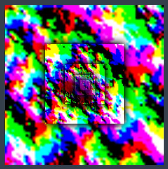
Each LOD is the same resolution (256x256 here), configured on the OceanRenderer script. In this example the largest LOD covers a large area (4km squared), and the most detail LOD provides plenty of resolution close to the viewer. These textures are visualised in the Debug GUI on the right hand side of the screen:
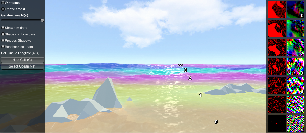
In the above screenshot the foam data is also visualised (red textures), and the scale of each LOD is clearly visible by looking at the data contained within. In the rendering each LOD is given a false colour which shows how the LODs are arranged around the viewer and how they are scaled. Notice also the smooth blend between LODs - LOD data is always interpolated using this blend factor so that there are never pops are hard edges between different resolutions.
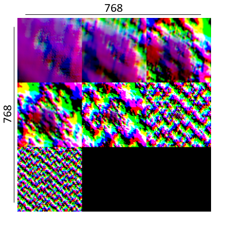
In this example the LODs cover a large area in the world with a very modest amount of data. To put this in perspective, the entire LOD chain in this case could be packed into a small texel area:
A final feature of the LOD system is that the LODs change scale with the viewpoint. From an elevated perspective, horizontal range is more important than fine wave details, and the opposite is true when near the surface. The OceanRenderer has min and max scale settings to set limits on this dynamic range.
When rendering the ocean, the various LOD data are sample for each vert and the vert is displaced. This means that the data is carried with the waves away from its rest position. For some data like wave foam this is fine and desirable. For other data such as the depth to the ocean floor, this is not a quantity that should move around with the waves and this can currently cause issues, such as shallow water appearing to move with the waves as in issue 96.
Can I sample the water height at a position from C#? Yes, see SampleHeightHelper. OceanRenderer uses this helper to get the height of the viewer above the water, and makes this viewer height available via the ViewerHeightAboveWater property.
Can I trigger something when an object is above or under the ocean surface without any scripting knowledge? The OceanSampleHeightEvents can be used for this purpose. It will invoke a UnityEvent when the attached game object is above or below the ocean surface once per state change.
Is Crest well suited for medium-to-low powered mobile devices? Crest is built to be performant by design and has numerous quality/performance levers. However it is also built to be very flexible and powerful and as such can not compete with a minimal, mobile-centric ocean renderer such as the one in the BoatAttack project. Therefore we target Crest at PC/console platforms.
Which platforms does Crest support? Testing occurs primarily on Windows. We have users targeting Windows, Mac, Linux, PS4, XboxOne, Switch and iOS/Android. Performance is a challenge on Switch and mobile platforms - see the previous question. For additional platform notes, see Platform Support.
Is Crest well suited for localised bodies of water such as lakes? Currently Crest is currrently targeted towards large bodies of water. The water could be pushed down where it's not wanted which would allow it to achieve rivers and lakes to some extent.
Does Crest support third party sky assets? We have heard of Crest users using TrueSky, AzureSky. These may require some code to be inserted into the ocean shader - there is a comment referring to this, search Ocean.shader for 'Azure'.
Can Crest work in Edit mode in the Unity Editor, or only in Play mode? Currently it only works in Play mode. Some work has been done to make it work in Edit mode but more work/fixes/testing is needed. wave-harmonic#208
Can Crest work with multiplayer? Yes the animated waves are deterministic and easily synchronized. See discussion in wave-harmonic#75. However, the dynamic wave sim is not fully deterministic and can not currently be relied upon networked situations.
Can the density of the fog in the water be reduced? The density of the fog underwater can be controlled using the Fog Density parameter on the ocean material. This applies to both above water and underwater.
My terrain does not appear to affect the water - no shorelines or shallow water waves. This built-in render pipeline version of crest requires the Draw Instanced option on terrains to be disabled at start time. It can be re-enabled subsequently after the depth cache is populated. See issue #158.